CAMPAIGN: 4WD INDICATOR LIGHT WIRING (OSHAWA ASSY. PLANT)

Subject: 4WD INDICATOR LIGHT WIRING
Models: 1991 K 15-35 Pickups Built At Oshawa Truck Assembly Centre
General Motors of Canada has determined that on certain 1991 K 15-35 pickups built at the Oshawa Truck Assembly Centre, the front axle indicator light may not work as intended. An electrical feedback condition may allow the light to remain on when the transfer case is shifted from 4wd to 2wd. If the vehicle continues to be operated in 2wd, this feedback condition will fail the front axle engagement switch causing the light to go out. When the vehicle is again placed into 4wd, the light will not go on and the RWAL system will remain enabled (normally disabled in 4wd). If the RWAL is activated while in 4wd, a diagnostic code 5 will be set in the RWAL module. This disables the RWAL function and causes the brake warning light on the instrument panel to illuminate and remain on.
To correct this condition a new wiring harness and front axle engagement switch will be installed.
VEHICLES INVOLVED:
The following VIN's are included in this recall:
2GTEK19C0M1514539 2GCDK14HXM1142027 2GTFK24K1M1514543 2GCFK29K9M1142071 2GTEK14K1M1514550 2GCDK14H0M1142103 2GTEK19K4M1514552 2GCDK14H2M1142121 2GTFK29C3M1514559 2GCEK19K6M1142129 2GTEK19K7M1514562 2GCEK14K0M1142148 2GTFK24HXM1514609
All affected vehicles have been identified by the VIN listing provided to involved dealers with this bulletin. Any dealer not receiving a listing was not shipped any of the affected vehicles.
DEALER CAMPAIGN RESPONSIBILITY:
Dealers are to perform this campaign on all involved vehicles at no charge to owners, regardless of kilometres traveled, age of vehicle, or ownership, from this time forward.
Whenever a vehicle subject to this campaign is taken into your new or used vehicle inventory, or it is in your dealership for service, you are to ensure the campaign correction has been made before selling or releasing the vehicle.
CAMPAIGN PROCEDURE:
Refer to Section 4 of the Service Policies and Procedures Manual for the detailed procedure on handling Product Campaigns. Dealers are requested to complete the campaign on all transfers as soon as possible.
OWNER NOTIFICATION:
There will be no owner letter sent out with this campaign as it is anticipated the vehicles should still be in your new vehicle inventory and should be repaired prior to retail sale. If a unit has been retailed, in order to maintain customer satisfaction, contact the owner immediately and arrange to correct this condition on his/her vehicle.
PARTS INFORMATION:
Parts required to complete this campaign will be shipped to involved dealers on a no charge basis.
PARTS AND LABOUR CLAIM INFORMATION:
Credit for the campaign work performed will be paid upon receipt of a properly completed campaign claim card, RAPID terminal or DCS transmission in accordance with the following:
Repair Code Description Time Allowance ----------- ---------------------------- ------------- 1A Inspect - Correct wiring harness already installed. .3 No further action required.
2A Inspect and install new wiring harness and front .8 axle engagement switch.
Time allowance includes 0. 1 hour for dealer administrative detail associated with this campaign. An allowance of $43.00 is included in repair code 2A for parts handling.
SERVICE PROCEDURE:
INSPECTION:
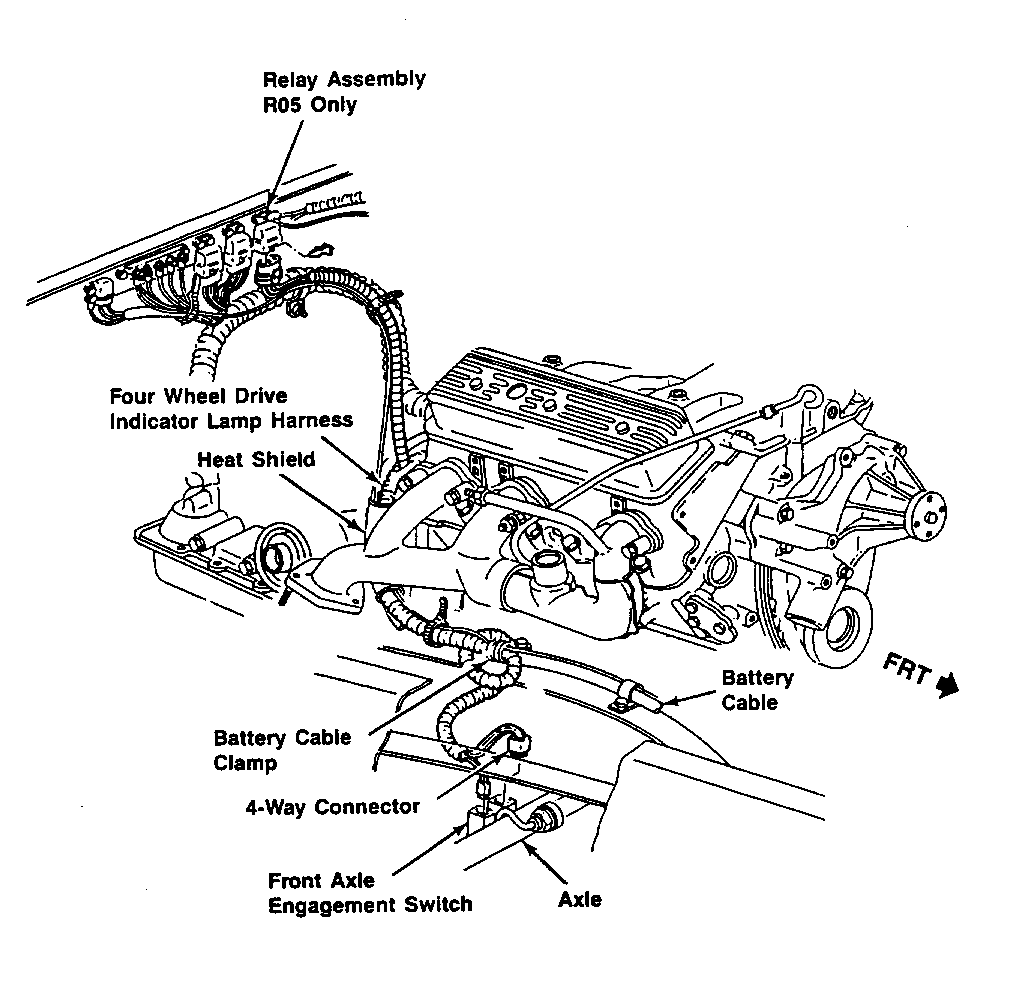
Raise the truck on a hoist and check the white 4-way connector at the front axle for wire colours (Figure 1). If the wire in cavity 'A' is brown, the truck has the correct wiring harness. If correct, proceed to Step 21 below. If the wire in cavity 'A' is blue, the harness and the front axle switch must be changed. Proceed to "Repair Section" below. Lower the truck.
REPAIR:
1. Prepare the truck; disconnect the negative battery cable.
2. Remove the clamp on the right frame rail that holds the battery cable and the wiring conduit from the front axle switch (Figure 1).
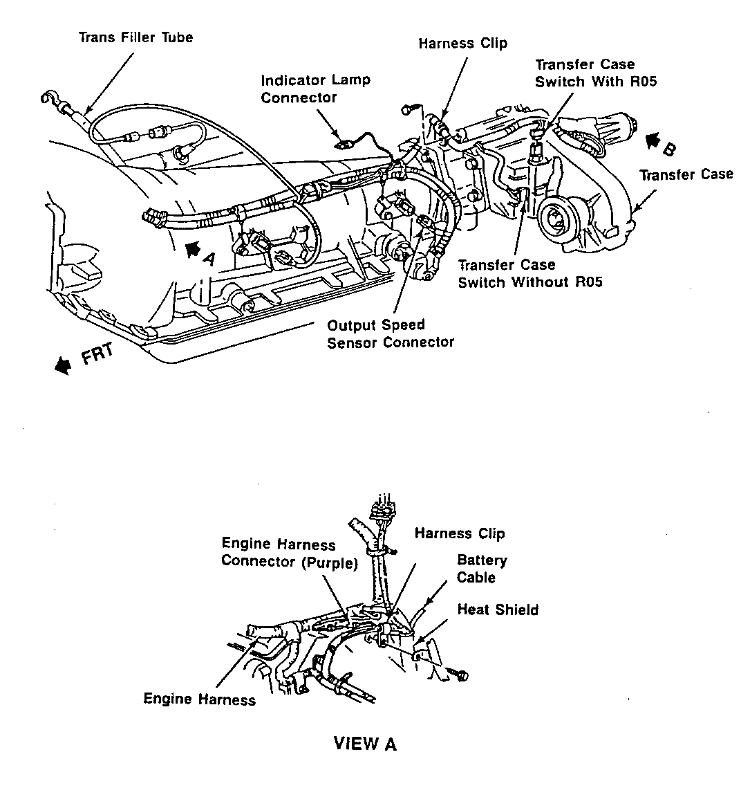
3. Disconnect the engine wiring harness connector behind the engine. This is a purple wire behind the engine, located approximately at the edge of the transmission bell housing (Figure 2, View A). This connector is more accessible from under the hood, but is viewed easier from under the truck. Thus you may want to raise the truck before disconnecting this connector.
4. Raise the truck on a hoist.
5. Disconnect the white 4-way connector to the front axle engagement switch, and disconnect the connector to the actuator. These are located right next to each other.
6. Open the harness clip that is bolted to the transmission bell housing just above the starter heat shield (Figure 2, View A), and open the harness clip located on the top right of the transfer case (Figure 2).
7. Disconnect the three connectors on the left side of the transmission, one which connects to the indicator lamp (attached to the floor pan), one which connects to the front side of the transfer case, and one to the output speed sensor (a brass coloured piece on the side of the transmission) (Figure 2). For trucks with MTI (4L80E) transmissions, there will be an additional two pin connector extension from the output speed sensor that should be disconnected.
8. Disconnect the harness from the back of the transfer case at the vehicle speed sensor.
9. Fabricate a pull wire about four to five feet long, and attach it to the front axle end of the harness.
10. Pull the harness through the starter heat shield from the transmission side of the truck, leaving the pull wire running through the heat shield.
11. Connect the new harness to the pull wire on the front axle connector side of the harness and tape over the two connectors to allow them to pass through the heat shield easily.
12. Pull the new harness through the heat shield toward the front axle side.
13. Remove and replace the front axle engagement switch.
14. Reconnect the harness to the front axle engagement switch and actuator, and tie strap the harness to the starter wires at the bottom of the starter heat shield.
IMPORTANT: The harness must be looped under the battery cable harness on the frame rail to prevent the harness from touching the exhaust manifold (Figure 1).
15. Connect the connectors to the left side of the transmission and the back of the transfer case, and reclip the harness to the clip at the top right of the transfer case and the clip bolted to the transmission bell housing.
16. Lower the truck, and reconnect the engine wiring harness connector (the purple wire) and the relay connector in the convenience centre.
17. Refasten the clamp on the right frame rail, keeping the harness routed under the battery cable and free of the exhaust manifold.
18. Reconnect the battery and road test to verify the proper operation of the 4-wheel indicator lamp.
19. Install "Campaign Identification Label."
INSTALLATION OF CAMPAIGN IDENTIFICATION LABEL
Clean surface of radiator upper mounting panel and apply a Campaign Identification Label. Make sure the correct campaign number is inserted on the label. This will indicate that the campaign has been completed.


General Motors bulletins are intended for use by professional technicians, not a "do-it-yourselfer". They are written to inform those technicians of conditions that may occur on some vehicles, or to provide information that could assist in the proper service of a vehicle. Properly trained technicians have the equipment, tools, safety instructions and know-how to do a job properly and safely. If a condition is described, do not assume that the bulletin applies to your vehicle, or that your vehicle will have that condition. See a General Motors dealer servicing your brand of General Motors vehicle for information on whether your vehicle may benefit from the information.
