Removal Procedure
Tools Required
J 38834 Balance Shaft Bearing Service Kit
- Disconnect the negative battery cable. Refer to
Caution: Unless directed otherwise, the ignition and start switch must be in the OFF or LOCK position, and all electrical loads must be OFF before servicing any electrical component. Disconnect the negative battery cable to prevent an electrical spark should a tool or equipment come in contact with an exposed electrical terminal. Failure to follow these precautions may result in personal injury and/or damage to the vehicle or its components.
in General Information. - Remove the air cleaner assembly and the intake duct. Refer to Air Cleaner in Engine Controls.
- Drain the cooling system. Refer to Draining and Refilling the Cooling System in Cooling and Radiator.
- Remove the air conditioning compressor, the bracket, and the accessory drive bracket. Refer to SECTION 1B.
- Remove the radiator. Refer to Radiator Replacement in Cooling and Radiator.
- Remove the air conditioning condenser. Refer to SECTION 1B.
- Remove the engine cooling fan. Refer to Fan and Fan Blade Clutch Replacement in Cooling and Radiator.
- Remove the water pump. Refer to Water Pump Replacement in Cooling and Radiator.
- Remove the crankshaft balancer. Refer to Crankshaft Balancer Replacement .
- Drain the engine oil.
- Remove the oil pan. Refer to Oil Pan Replacement .
- Remove the front cover. Refer to Engine Front Cover Replacement .
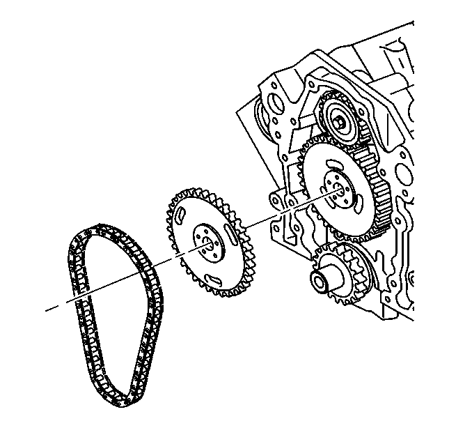
- Remove the camshaft sprocket bolts and the nut.
- Remove the timing chain, the camshaft sprocket, and the balance shaft drive gear.
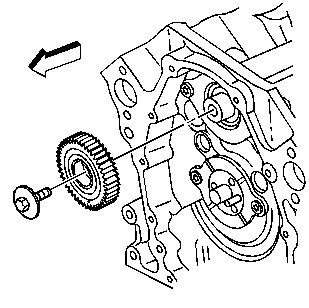
- Remove the balance shaft driven gear.
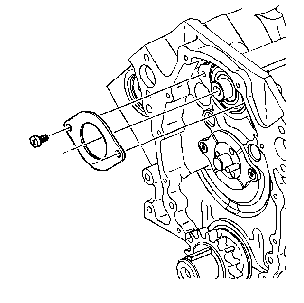
- Remove the balance shaft retainer.
- Remove the intake manifold. Refer to Intake Manifold Replacement .
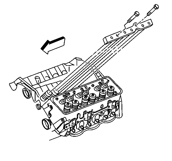
- Remove the valve lifter retainer.
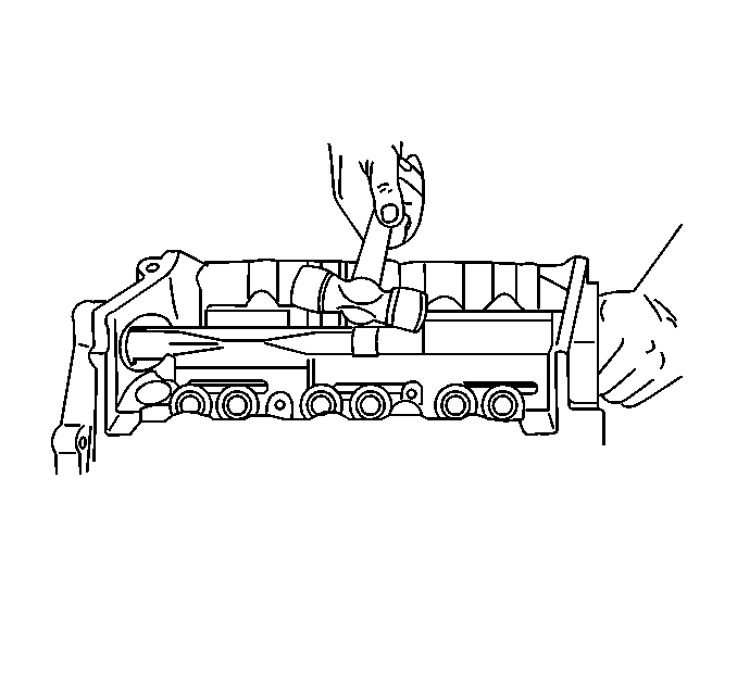
- Remove the balance shaft and the front bearing. Use a soft faced hammer.
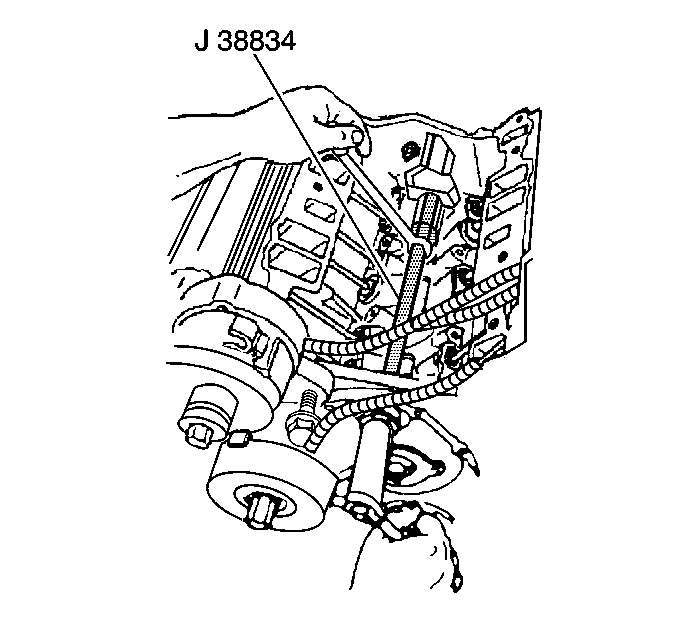
- Remove the balance shaft rear bearing. Use the J 38834
- Clean all traces of the old gasket material from the gasket sealing surfaces.
- Inspect the balance shaft drive and the driven gears for nicks and burrs.
Important: Use care when removing the front cover from the front of the oil pan seal.
Important:
• Service the balance shaft and the front bearing only as an assembly. • Use only the correct tools for bearing and shaft replacement. • Do not remove the front bearing from the balance shaft. • Service the balance shaft drive and driven gears only as a set.
The set includes the balance shaft driven gear bolt.
Installation Procedure
Tools Required
| • | J 38834 Balance Shaft Bearing Service Kit |
| • | J 36996 Shaft Installer |
| • | J 8092 Driver Handle |
| • | J 36660-A Torque/Angle Meter |
- Dip the balance shaft rear bearing in clean engine oil before installation.
- Install the balance shaft rear bearing. Use the J 38834
- Dip the front balance shaft bearing into clean engine oil before assembly.
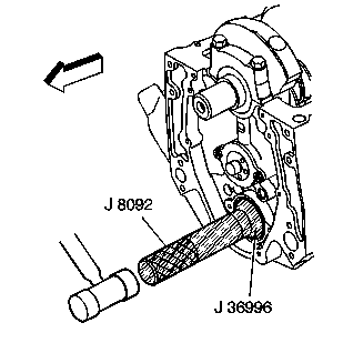
- Install the balance shaft into the block. Use the J 36996 and the J 8092
- Install the balance shaft bearing retainer.
- Install the balance shaft bearing retainer bolts.
- Install the balance shaft driven gear.
- Install the balance shaft driven gear bolt.
- Install the valve lifter retainer.
- Rotate the balance shaft by hand in order to make sure that there is clearance between the balance shaft and the valve lifter retainer. Replace the valve lifter retainer if necessary.
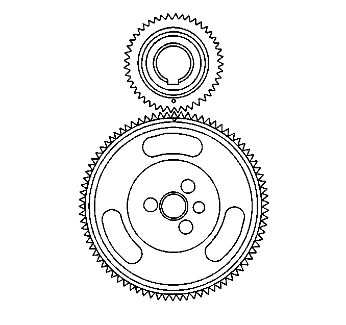
- Turn the camshaft with the balance shaft drive gear temporarily installed. The timing mark on the drive gear must be straight up.
- With the balance shaft drive gear removed, turn the balance shaft so the timing mark on the driven gear points straight down.
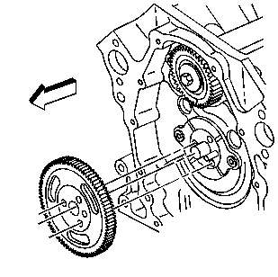
- Install the balance shaft drive gear onto the camshaft.
- Install the balance shaft drive gear retaining stud.
- Install the intake manifold. Refer to Intake Manifold Replacement .
- Install the camshaft sprocket and the timing chain.
- Install the camshaft sprocket bolts.
- Install the distributor. Refer to Distributor Replacement in Ignition System.
- Install the front cover. Refer to Engine Front Cover Replacement .
- Install the oil pan. Refer to Oil Pan Replacement .
- Install the crankshaft balancer. Refer to Crankshaft Balancer Replacement .
- Install the accessory drive pulley. Refer to Drive Belt Replacement .
- Install the water pump. Refer to Water Pump Replacement in Cooling and Radiator.
- Install the engine cooling fan. Refer to Fan and Fan Blade Clutch Replacement in Cooling and Radiator.
- Install the air conditioning condenser. Refer to SECTION 1B.
- Install the radiator. Refer to Radiator Replacement in Cooling and Radiator.
- Install the air conditioning compressor, the bracket, and the accessory drive bracket. Refer to SECTION 1B.
- Install the air cleaner assembly and the intake duct. Refer to Air Cleaner in Engine Controls.
- Connect the negative battery cable.
- Fill the crankcase with the proper quantity and grade of engine oil. Refer to SECTION 0B.
- Fill the cooling system with the proper quantity and grade of engine coolant. Refer to Specifications in Cooling and Radiator.
- Charge the air conditioning system. Refer to SECTION 1B.

Tighten
Tighten the bolts to 14 N·m (120 lb in).
Notice: Use the correct fastener in the correct location. Replacement fasteners must be the correct part number for that application. Fasteners requiring replacement or fasteners requiring the use of thread locking compound or sealant are identified in the service procedure. Do not use paints, lubricants, or corrosion inhibitors on fasteners or fastener joint surfaces unless specified. These coatings affect fastener torque and joint clamping force and may damage the fastener. Use the correct tightening sequence and specifications when installing fasteners in order to avoid damage to parts and systems.

Tighten
Tighten the balance shaft driven gear bolt to 20 N·m (15 lb ft.)
plus an additional turn of 35 degrees using the J 36660-A
.

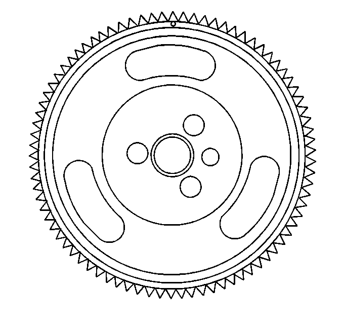
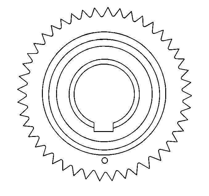
Important: Be sure that the timing marks on the balance shaft drive gear and the driven gear line up dot to dot.
Tighten
Tighten the stud to 16 N·m (12 lb ft).
Important: Line up the timing marks on the camshaft sprocket and the crankshaft sprocket dot to dot. When these marks are lined up dot to dot, the number four cylinder is at the top dead center of its compression stroke. Position the distributor rotor facing the cap hold down mount nearest the flat side of the housing.

Tighten
Tighten the camshaft sprocket bolts to 28 N·m (21 lb ft).
Important: Use care when engaging the front of the oil pan seal with the bottom of the front cover. Lubricate the front of the oil pan seal with engine oil to aid in reassembly.
