Removal Procedure
Tools Required
J 39087 Crankshaft Balancer (External) Remover and Installer
- Remove the belt. Refer to Drive Belt Replacement .
- Remove the upper shroud. Refer to Fan Shroud Replacement in Cooling and Radiator.
- Remove the engine cooling fan. Refer to Fan and Fan Blade Clutch Replacement in Cooling and Radiator.
- Raise the vehicle.
- Remove the lower shroud. Refer to Fan Shroud Replacement in Cooling and Radiator.
- Remove the accessory drive pulley.
- Remove the crankshaft balancer (External) bolt.
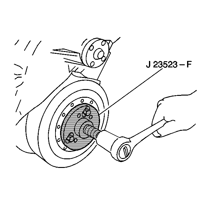
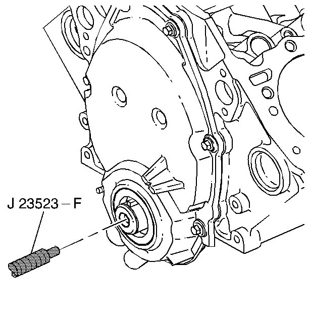
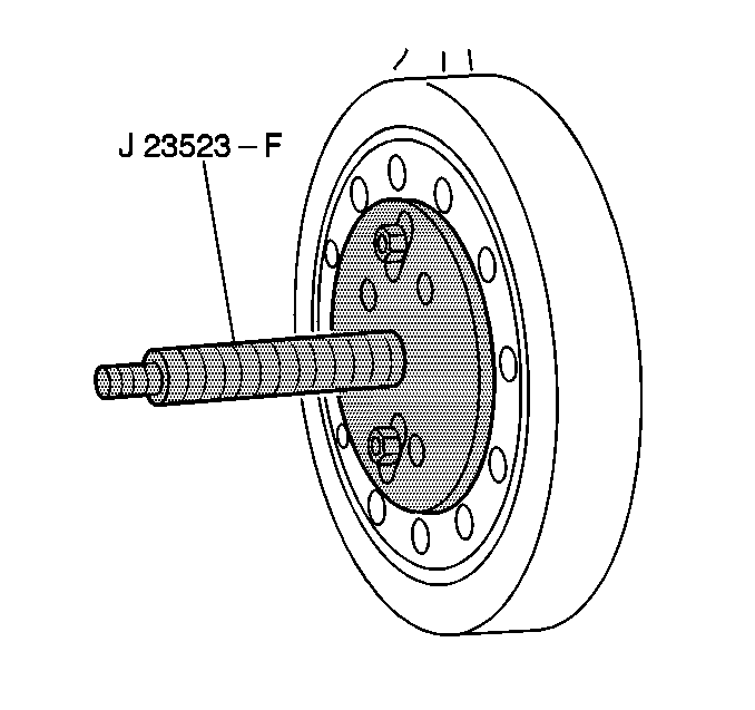
- Remove the crankshaft balancer (External). Use the J 23523-F .
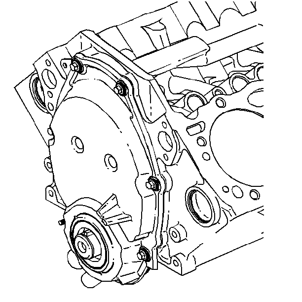
- Remove the crankshaft front oil seal. Pry out the seal with a large screwdriver. Take care not to distort the front cover.
- Remove the crankshaft key, if necessary.
- Inspect the oil seal contact area on the crankshaft balancer (External) shaft for grooving and roughness. Replace the crankshaft balancer if necessary.
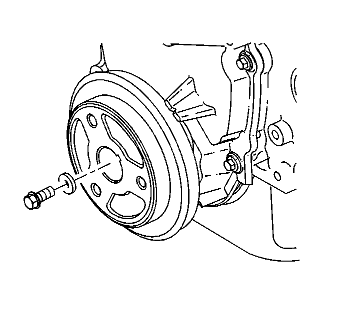
Notice: The inertial weight section of the balancer is assembled to the hub with a rubber type material. The correct removal procedure must be followed or movement of the inertial weight section of the hub will destroy the tuning of the balancer.
Installation Procedure
Tools Required
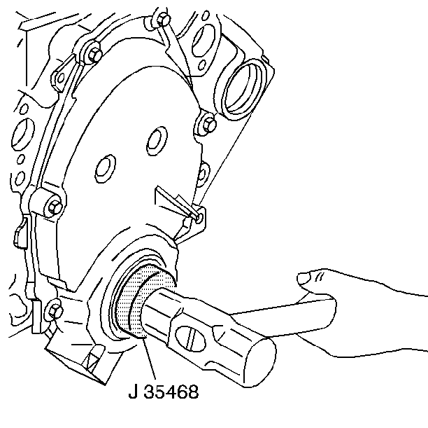
J 35468 Front Cover Seal Installer
- Install the crankshaft key, if removed.
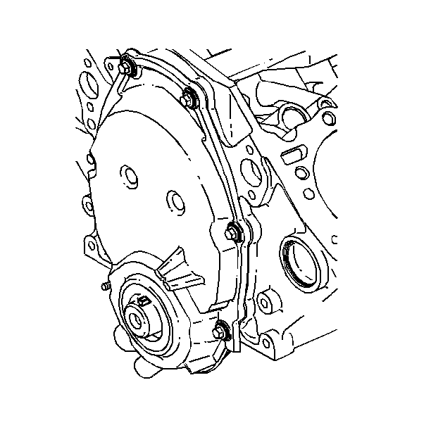
- Install the crankshaft front oil seal. Use the J 35468 . The open end of the seal faces inside the engine.
- Coat the seal lips with engine oil.
- Thread the stud fully into the tapped hole in the crankshaft.
- Install the crankshaft balancer (External) over the end of the stud.
- Align the keyway in the crankshaft balancer (External) shaft with the crankshaft key.
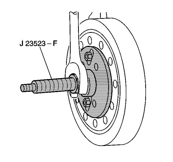
- Install the bearing, the washer, and the nut.
- Turn the nut to push the crankshaft balancer (External) into place.
- Remove the tool.
- Use a small amount of RTV sealant in order to seal the crankshaft balancer (External) key to the crankshaft keyway.
- Install the crankshaft balancer bolt and the washer.
- Lower the vehicle.
- Install the accessory drive pulley.
- Install the lower shroud. Refer to Fan Shroud Replacement in Cooling and Radiator.
- Install the engine cooling fan. Refer to Fan and Fan Blade Clutch Replacement in Cooling and Radiator.
- Install the upper shroud. Refer to Fan Shroud Replacement in Cooling and Radiator.
- Install the belt. Refer to Drive Belt Replacement .

Notice: The inertial weight section of the balancer is assembled to the hub with a rubber type material. The correct removal procedure must be followed or movement of the inertial weight section of the hub will destroy the tuning of the balancer.

Tighten
Tighten the bolt to 95 N·m (70 lb ft).
Notice: Use the correct fastener in the correct location. Replacement fasteners must be the correct part number for that application. Fasteners requiring replacement or fasteners requiring the use of thread locking compound or sealant are identified in the service procedure. Do not use paints, lubricants, or corrosion inhibitors on fasteners or fastener joint surfaces unless specified. These coatings affect fastener torque and joint clamping force and may damage the fastener. Use the correct tightening sequence and specifications when installing fasteners in order to avoid damage to parts and systems.
