Removal Procedure
- Drain the cooling system.
- Remove the water pump. Refer to Cooling and Radiator.
- Rotate the engine until the timing marks are aligned.
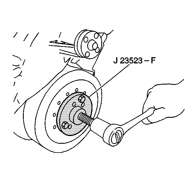
- Remove the crankshaft balancer. Refer to Crankshaft Balancer Replacement .
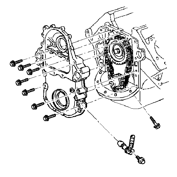
- Remove the crankshaft position sensor.
- Remove the engine front cover to oil pan bolts.
- Remove the fuel return line clips.
- Remove the front cover for the fuel injection pump drive gear.
- Remove the fuel injection pump gear.
- Remove the fuel injection pump retaining nuts.
- Remove the engine front cover and bolts.
- Remove the engine front cover oil seal. Pry the oil seal out with a screwdriver.
- Clean the RTV from the oil pan sealing surface and the sealing surfaces on the engine front cover.
- Inspect the engine front cover for cracks or damage to the sealing surfaces.
Notice: Perform TDC Offset Recovery procedure if the timing chain, timing gears, engine front cover, crankshaft position sensor, crankshaft or other components affecting the timing are replaced.


Important: Mark the fuel line clips, so that they can be re-installed on the proper stud.

Installation Procedure
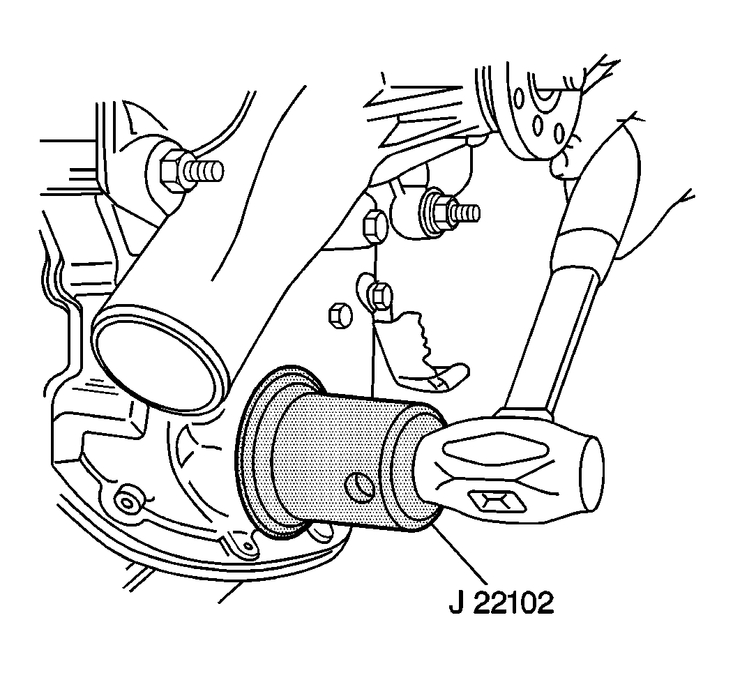
- Install the new engine front cover oil seal to the engine front cover. Use the J 22102 .
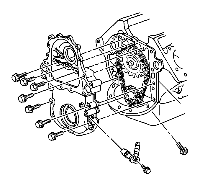
- Install the engine front cover to the engine.
- Install the attaching bolts and the fuel injection pump studs.
- Install the fuel injection pump gear.
- Install the fuel injection pump gear bolts and align the timing marks.
- Install the front cover fuel injection drive gear.
- Install the fuel return line clip.
- Install the crankshaft position sensor.
- Install the engine front cover.
- Install the crankshaft balancer.
- Fill the cooling system with the proper quantity and grade of coolant. Refer to Maintenance and Lubrication.
- Reset the fuel injection pump timing. Refer to Engine Controls.

| • | Apply a 2 mm (3/32 in) bead of anaerobic sealant GM P/N 1052357 or equivalent to the engine front cover. |
| • | Apply a 5 mm (3/16 in) bead of RTV sealant to the engine front cover sealing the surface that mates against the oil pan. |
Tighten
Tighten the nuts to 40 N·m (30 lb ft).
Notice: Use the correct fastener in the correct location. Replacement fasteners must be the correct part number for that application. Fasteners requiring replacement or fasteners requiring the use of thread locking compound or sealant are identified in the service procedure. Do not use paints, lubricants, or corrosion inhibitors on fasteners or fastener joint surfaces unless specified. These coatings affect fastener torque and joint clamping force and may damage the fastener. Use the correct tightening sequence and specifications when installing fasteners in order to avoid damage to parts and systems.

Tighten
Tighten the bolts to 25 N·m (20 lb ft).
Important: Check the marks on the fuel line clips made during removal. Ensure that the fuel line clips are re-installed on the proper studs.

