Crankshaft and Bearing Installation L65
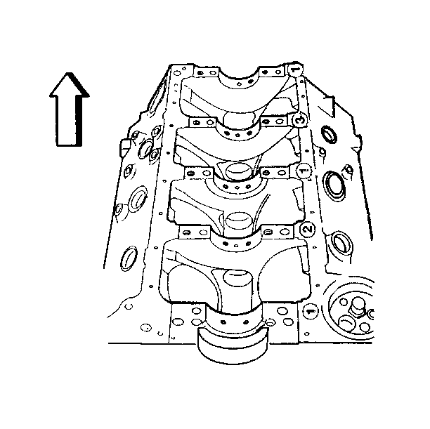
There are five crankshaft bearings numbered 1 through 5, as viewed from the front of the engine. There is an arrow on each bearing cap that points toward the front of the engine. The center crankshaft bearing, number three, is the thrust bearing.
The upper crankshaft bearing inserts all have an oil groove and a oil gallery hole from the block in the center of the groove. The upper crankshaft bearing inserts also have additional holes in the oil groove at 10 o'clock and 2 o'clock to provide oil to the oil spray nozzles. The oil spray nozzles are mounted in the crankshaft bearing bulk heads. The lower bearing inserts do not have an oil groove or holes.
During initial assembly, the crankshaft bearings are select-fitted to each of the five crankshaft bearing bores. The total diameter size range of crankshaft bearing bores 1 through 5 is 79.826-79.850 mm (3.145-3.146 in). This range divides into three sizes, represented by the size numbers 1, 2 or 3. The proper size number is then stamped on the pan rail at the corresponding crankshaft bearing bulk head.
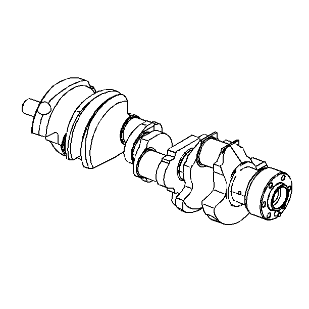
The crankshaft is color-marked in red/orange, blue or white, near each crankshaft bearing journal. Cross-referencing the size number on the pan rail with the color on the crankshaft indicates the proper bearing selection.
| • |
|
| • |
| • |
| - | Crankshaft bearing numbers 1, 2, 3 and 4: 0.045-0.083 mm (0.0018-0.0033 in). |
| - | Crankshaft bearing number 5: 0.055-0.093 mm (0.0022-0.0037 in). |
- Install the upper crankshaft bearing inserts to the block.
- Install the lower crankshaft bearing inserts to the crankshaft bearing caps.
- Apply engine oil to the crankshaft bearing inner surfaces.
- Install the crankshaft.
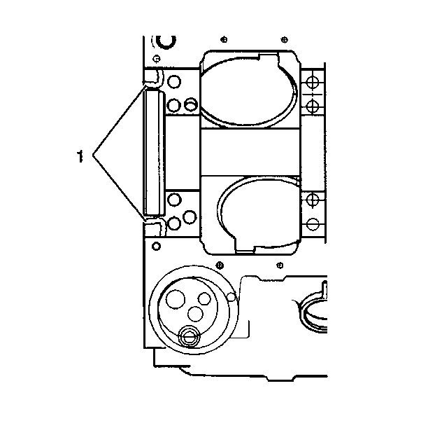
- Apply a 1/8 inch bead of gasket maker (1), GM P/N 1052942, or equivalent, on each side of the rear crankshaft bearing cap area.
- Apply engine oil to the crankshaft bearing cap bolt threads.
- Install the number 1, 2, 4, and 5 crankshaft bearing caps and bearing by tapping into place with a brass or leather mallet.
- Apply engine oil to the crankshaft bearing cap bolt threads.
- Install the crankshaft bearing cap inner 12 mm bolts.
- Install the number three crankshaft bearing cap and the bearing (thrust bearing) by tapping into place with a brass or leather mallet.
- Install the crankshaft bearing cap inner 12 mm bolts.
- Tap the end of the crankshaft first rearward then forward with a lead hammer to line up the crankshaft bearing and the crankshaft thrust surfaces.
- Measure the crankshaft end play with the crankshaft forced forward. Measure at the front end of the number three crankshaft bearing with a feeler gauge. The proper clearance is 0.10-0.25 mm (0.004-0.0010 in).
- Tighten all crankshaft bearing cap bolts in the following sequence:
- Retighten the inner 12 mm bolts to 75 N·m (55 lb ft).
- Tighten the inner 12 mm bolts an additional 90 degrees.
- Tighten the outer 12 mm bolts (crankshaft bearing caps 1 and 5) to 65 N·m (48 lb ft).
- Retighten the outer 12 mm bolts (crankshaft bearing caps 1 and 5) to 65 N·m (48 lb ft).
- Tighten the outer 12 mm bolts an additional 90 degrees.
- Tighten the outer 10 mm bolts (crankshaft bearing caps 2, 3, and 4) to 40 N·m (30 lb ft).
- Inspect the crankshaft for binding.
- Try turning the crankshaft to check for binding. If the crankshaft does not turn freely, loosen the crankshaft bearing cap bolts, one pair at a time, until the tight bearing is located.
- Burrs on the crankshaft bearing cap, foreign matter between the insert and the block or the crankshaft bearing cap, or a faulty insert could cause a lack of clearance at the bearing.
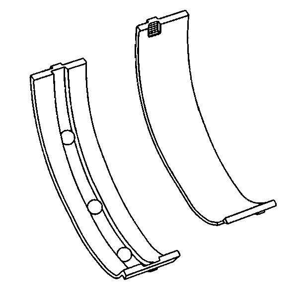
Important: The upper crankshaft bearing inserts must have holes for the piston oil nozzles, or damage to the engine could result. All engines were assembled with three-hole upper crankshaft bearing inserts in positions 1, 2, 3 and 4, and with a two-hole upper crankshaft bearing insert in position 5. Replace the upper crankshaft bearing inserts with the same type as originally installed.
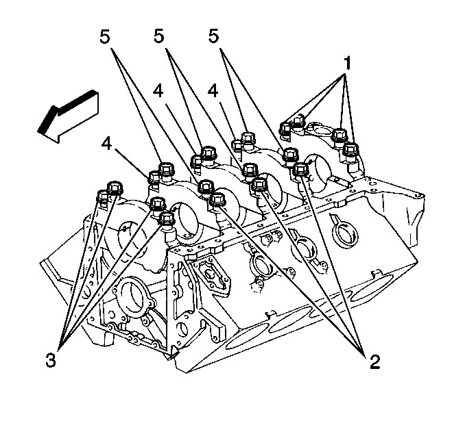
Important: Crankshaft bearing cap bolt sizes are as follows:
• All inner crankshaft bearing cap bolts on crankshaft bearing caps
1, 2, 3, 4, and 5 are the long 12 mm bolts. • All outer crankshaft bearing cap bolts on crankshaft bearing caps
1 and 5 are the short 12 mm bolts. • All outer crankshaft bearing cap bolts on crankshaft bearing caps
2, 3, and 4 are the 10 mm bolts.
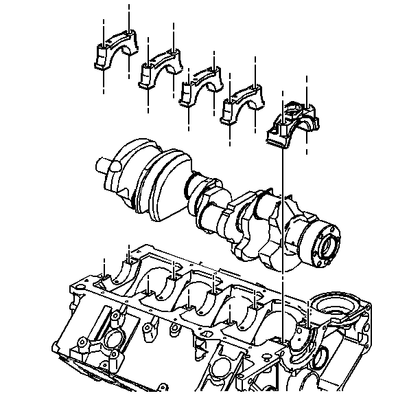
Notice: The crankshaft bearing caps are to be tapped into place with a brass or leather mallet before the attaching bolts are installed. Do not use the attaching bolts to pull the crankshaft bearing caps into their seats, as this may damage the bearing cap and/or block.
Notice: Use the correct fastener in the correct location. Replacement fasteners must be the correct part number for that application. Fasteners requiring replacement or fasteners requiring the use of thread locking compound or sealant are identified in the service procedure. Do not use paints, lubricants, or corrosion inhibitors on fasteners or fastener joint surfaces unless specified. These coatings affect fastener torque and joint clamping force and may damage the fastener. Use the correct tightening sequence and specifications when installing fasteners in order to avoid damage to parts and systems.
Tighten
Tighten the inner 12 mm bolts to 75 N·m (55 lb ft).
Tighten
Tighten the inner 12 mm bolts to 14 N·m (10 lb ft).
Tighten
Tighten the inner 12 mm bolts to 75 N·m (55 lb ft).
Tighten
DO NOT tighten the outer 10 mm bolts (crankshaft bearing caps 2, 3, and 4) an additional 90 degrees.
