Tools Required
J 29873 Nozzle Socket
- Install the fuel injection pump and gasket with the ESO solenoid pointed straight up.
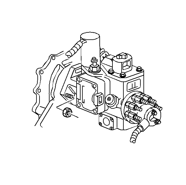
- Install the fuel injection pump nuts.
- Install the fuel injection pump gear. Align the slot in the fuel injection pump gear with the locating pin on the fuel injection pump hub.
- Install the fuel injection pump gear retaining bolts.
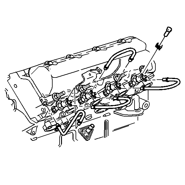
- Apply a thin coating of GM P/N 12371386 (Canadian P/N 89021945), or equivalent, to the threads of the injection nozzle.
- Install the injection nozzle and gasket, using the J 29873 .
- Install the injection line brackets.
- Install the injection lines to the pump.
- Install the injection lines to the nozzles.
- Install the injection line clips to the brackets.
- Install the fuel inlet line to the fuel injection pump.
- Install the fuel return hose to the fuel injection pump.
- Install the fuel return line brackets on the front left and the front right side rocker covers.
- Install the fuel return hoses at the injector nozzles.
- Install the clamps.
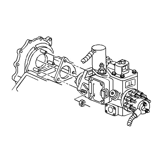
Important: Never rotate the engine with the starter, the starter location engine rotation fixture, or with the wrench from the front of the engine with the fuel injection pump removed. The loose fuel pump drive gear could become lodged in the front cover and cause gear tooth distress and shear the camshaft drive gear. Align the camshaft gear timing marks before installing the fuel injection pump drive gear.
Notice: Use the correct fastener in the correct location. Replacement fasteners must be the correct part number for that application. Fasteners requiring replacement or fasteners requiring the use of thread locking compound or sealant are identified in the service procedure. Do not use paints, lubricants, or corrosion inhibitors on fasteners or fastener joint surfaces unless specified. These coatings affect fastener torque and joint clamping force and may damage the fastener. Use the correct tightening sequence and specifications when installing fasteners in order to avoid damage to parts and systems.
Tighten
Tighten the nuts to 40 N·m (30 lb ft).
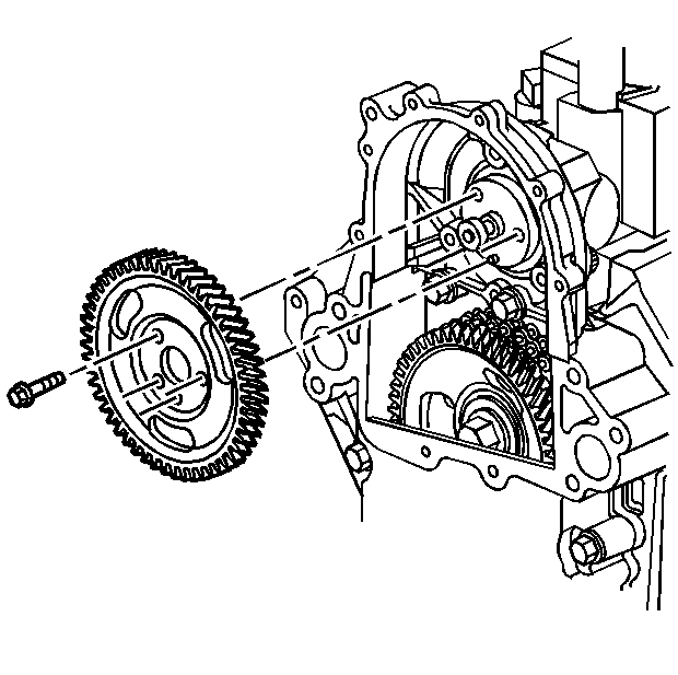
Important: Align the timing marks. Be certain the mark on the fuel injection pump gear is aligned with the mark on the camshaft gear. For the proper timing of the fuel injection pump, the cam gear timing mark must be in the 12 o'clock position. Rotate the crankshaft to bring the cam gear timing mark up to the 12 o'clock position.
Tighten
Tighten the bolts to 25 N·m (20 lb ft).
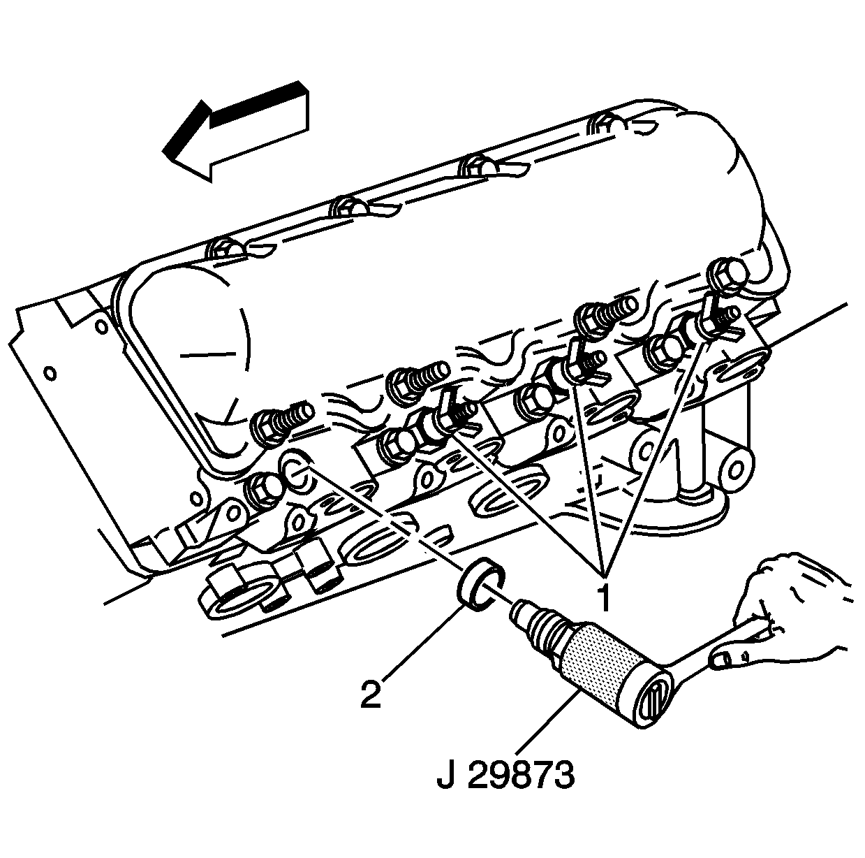
Notice: In order to remove or install an injection nozzle, use the J 29873 on the 30-mm portion of the nozzle. Failure to use the 30-mm hex portion will result in damage to the injection nozzle.
Tighten
Tighten the nozzle to 80 N·m (59 lb ft).
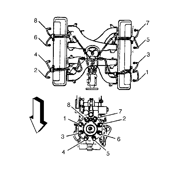
Important:
• Uncap the injection lines before assembly. • Install the injection lines in the correct position. • Do not bend the injection lines.
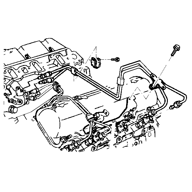
Important:
• Uncap the injection lines before assembly. • Install the injection lines in the correct position. • Do not bend the injection lines.
Tighten
Tighten the injection line fittings to 36 N·m (28 lb ft).
