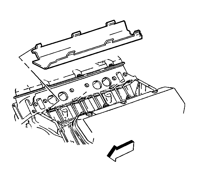
- Install the splash shield.
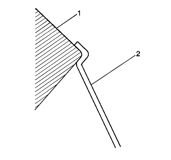
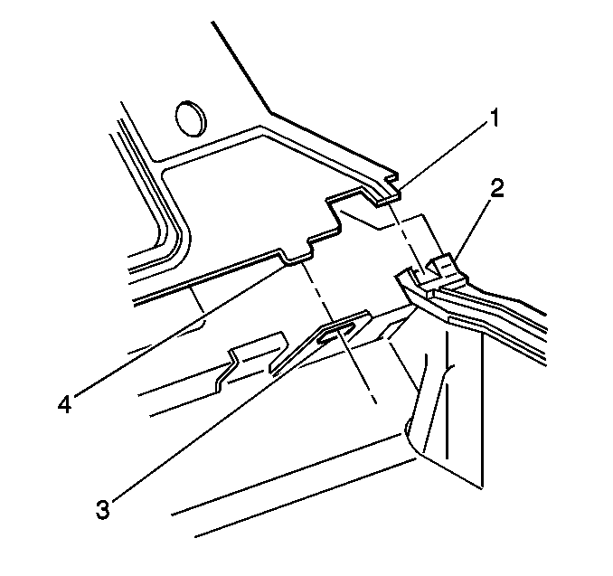
- Ensure the splash shield (2) snap fits between the cylinder heads (1).
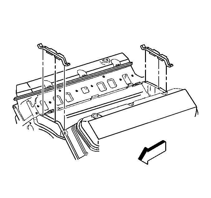
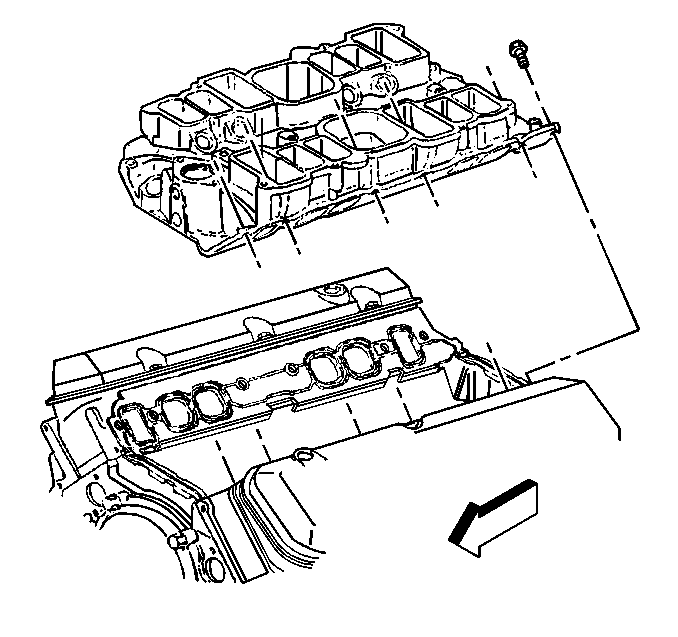
- Install the new lower intake manifold seals.
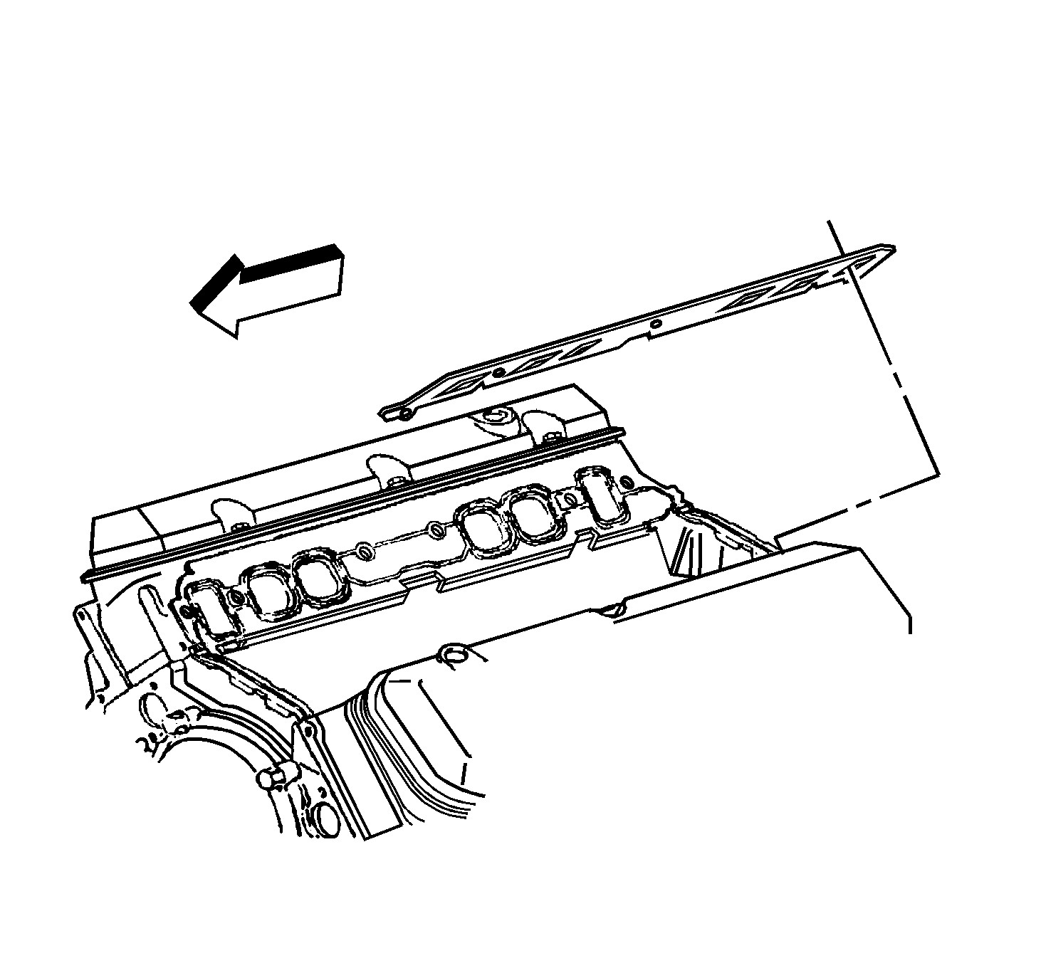
- Install the new lower intake manifold gaskets onto the cylinder heads.
- Ensure the lower intake manifold gasket tabs (4) align with the hole in the head gasket (3).
- Ensure the lower intake manifold gasket tabs (1) align with the slot in the lower intake manifold seals (2).
- Install the lower intake manifold onto the engine block.
- Apply sealer GM P/N 12345382 or equivalent to a minimum of eight threads of the lower intake manifold bolts.
- Install the lower intake manifold bolts.
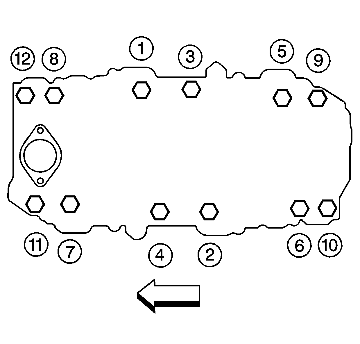
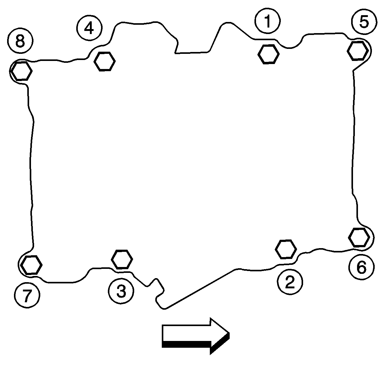
- Tighten the lower intake manifold bolts (1-8) a first pass in sequence to 30 N·m (22 lb ft).
- Tighten the lower intake manifold bolts (1-8) a final pass in sequence to 40 N·m (30 lb ft).
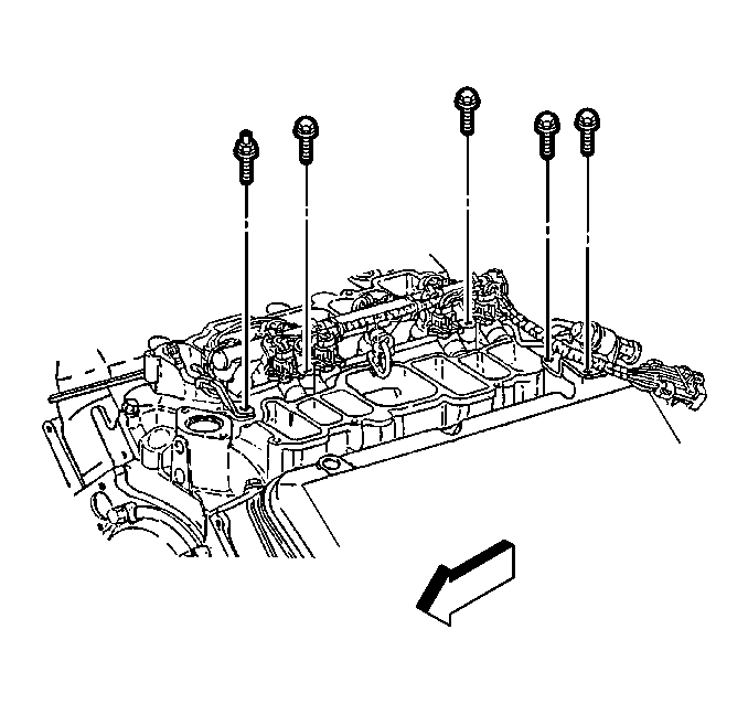
- Install the fuel rail assembly into the intake manifold. Tilt the rail assembly to install the injectors.
- Install the fuel rail bolts and stud.
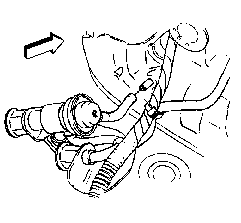
- Connect the fuel injector regulator vacuum hose connection to the intake manifold fitting.
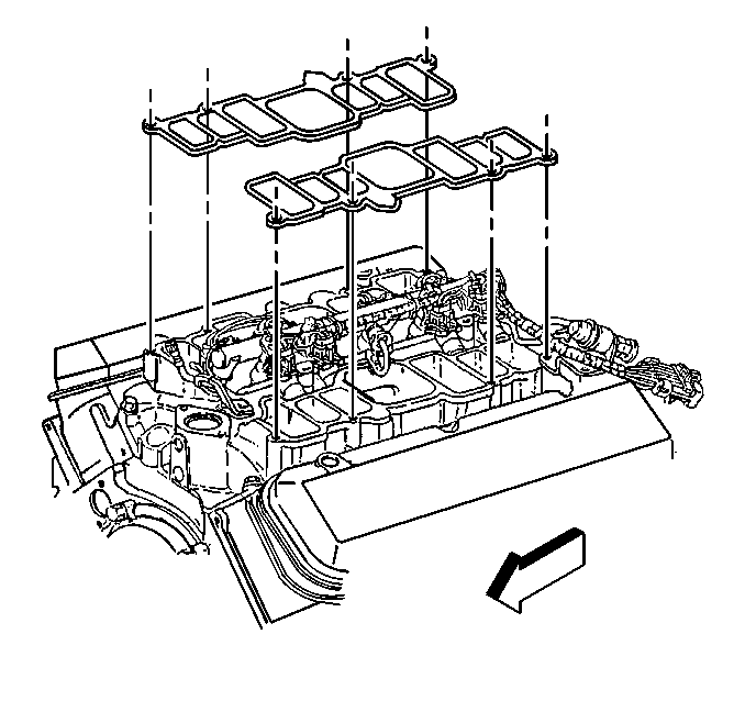
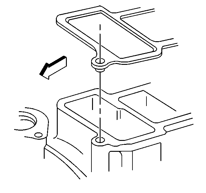
- Install the new upper intake manifold gaskets.
- Ensure the locating tabs on the gasket fit into the lower intake manifold counterbores.
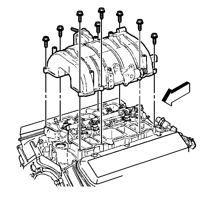
- Install the upper intake manifold.
- Apply sealer GM P/N 12345493 or equivalent to a minimum of eight threads of the upper intake manifold bolts.
- Install the upper intake manifold bolts.
- Tighten the upper intake manifold bolts (1-8) a first pass in sequence to 8 N·m (71 lb in).
- Tighten the upper intake manifold bolts (1-8) a final pass in sequence to 18 N·m (13 lb ft).
Notice: Use the correct fastener in the correct location. Replacement fasteners must be the correct part number for that application. Fasteners requiring replacement or fasteners requiring the use of thread locking compound or sealant are identified in the service procedure. Do not use paints, lubricants, or corrosion inhibitors on fasteners or fastener joint surfaces unless specified. These coatings affect fastener torque and joint clamping force and may damage the fastener. Use the correct tightening sequence and specifications when installing fasteners in order to avoid damage to parts and systems.
Tighten
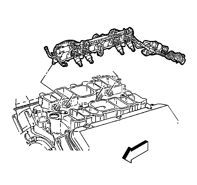
Important: Lubricate the injector O-ring seals with clean engine oil and install onto the spray tip end of each injector.
Tighten
| • | Tighten the fuel rail bolts to 10 N·m (89 lb in). |
| • | Tighten the fuel rail stud to 25 N·m (18 lb ft). |
Tighten
