- Bring cylinder number one piston to TDC (Top Dead Center) of the compression stroke.
- Remove the distributor cap screws to expose the rotor.
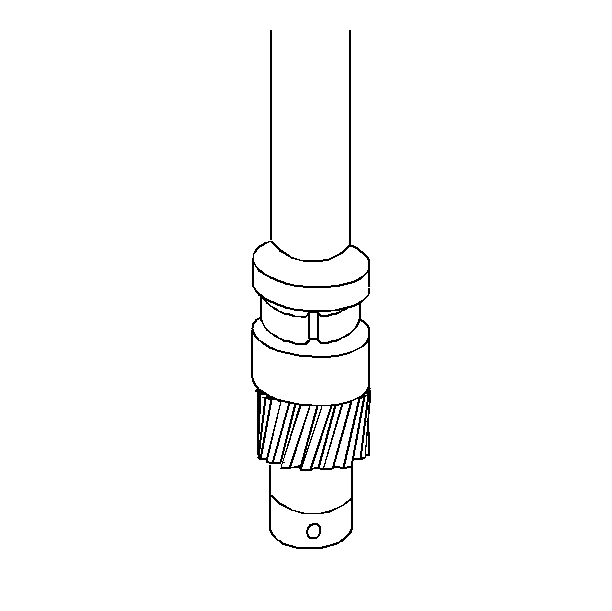
- Align the pre-drilled indent hole in the distributor driven gear with the white painted alignment line on the lower portion of the shaft housing.
- Using a long screw driver, align the oil pump drive shaft in the engine with the mating drive tab at the end of the distributor shaft.
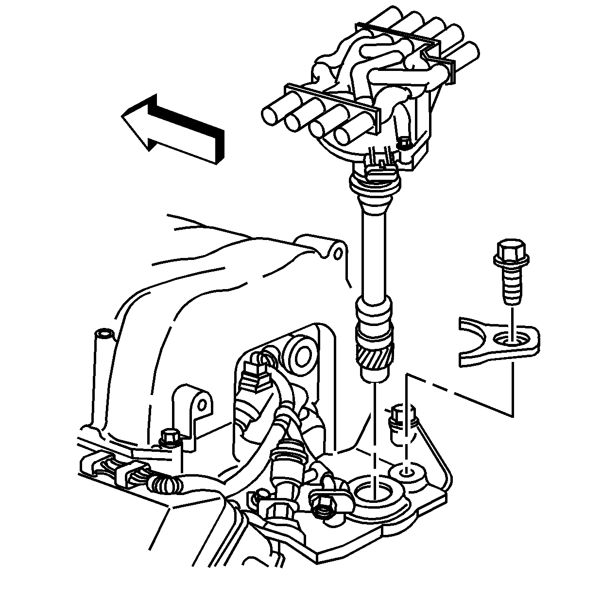
- Guide the distributor into place.
- Make sure the distributor is fully seated in the engine.
- Once the distributor is fully seated, the rotor segment should be aligned with the pointer cast into the distributor base.
- Install the distributor hold down clamp bolt to the lower intake manifold.
- Install the distributor cap.
- Install the distributor cap screws. Do not overtighten.
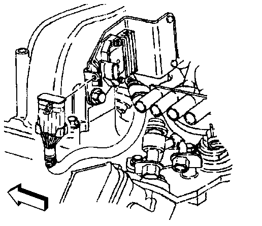
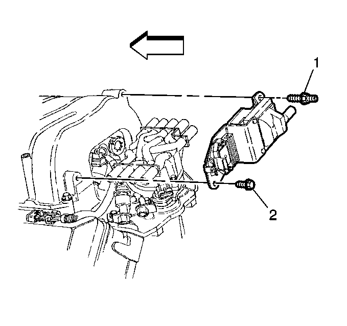
- Install the ignition coil to the upper intake manifold.
- Install the ignition coil bracket bolt (2) and stud (1) to the upper intake manifold.
- Connect the fuel injector wiring harness connector to the ignition coil bracket.
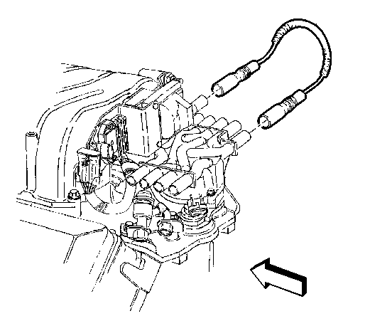
- Connect the ignition coil wire to the distributor and ignition coil.
Important: Distributor cap screws are not captured in the distributor cap.
| 6.1. | If the distributor is not fully seated, the oil pump drive shaft may not be aligned with the mating drive tab at the end of the distributor shaft. |
| 6.2. | Remove the distributor and align the oil pump drive shaft as stated above. |
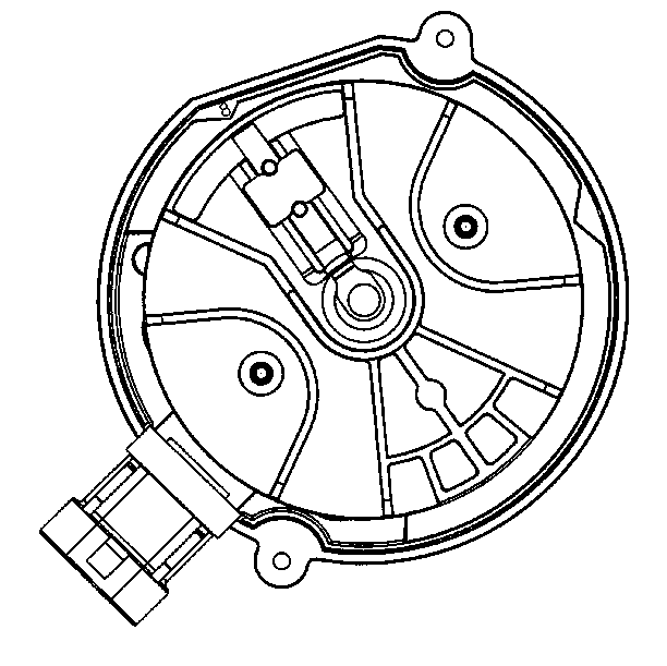
| • | The pointer has a (8) cast into it, indicating the distributor is for an eight cylinder engine. |
| • | If the rotor segment does not come out within a few degrees of the pointer (8), the gear mesh between the distributor and the camshaft may be OFF by a tooth or more. |
| • | If this is the case repeat this procedure to achieve the proper alignment. |

Notice: Use the correct fastener in the correct location. Replacement fasteners must be the correct part number for that application. Fasteners requiring replacement or fasteners requiring the use of thread locking compound or sealant are identified in the service procedure. Do not use paints, lubricants, or corrosion inhibitors on fasteners or fastener joint surfaces unless specified. These coatings affect fastener torque and joint clamping force and may damage the fastener. Use the correct tightening sequence and specifications when installing fasteners in order to avoid damage to parts and systems.
Tighten
Tighten the distributor clamp bolt to 33 N·m (24 lb ft).
Tighten
Tighten the cap holding screws to 5 N·m (40 lb in).
Tighten
Tighten ignition coil bracket bolt (2) and stud (1) to 25 N·m
(18 lb ft).
