Intake Manifold Assemble Lower
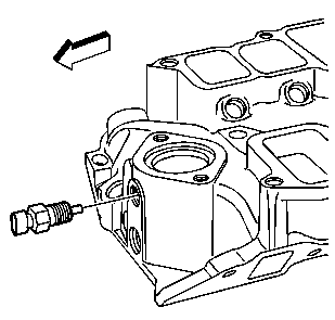
- Install the ECT sensor using sealant GM P/N 12346004 or equivalent, if removed.
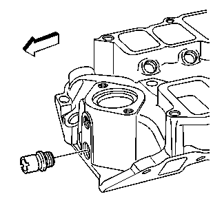
- Install the thermostat bypass hose fitting using sealant GM P/N 12346004 or equivalent, if removed.
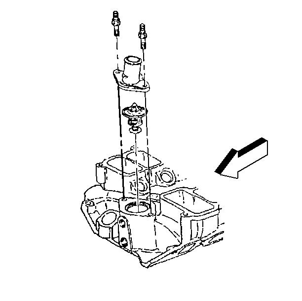
- Install the thermostat and NEW thermostat seal.
- Install the coolant outlet housing.
- Install the coolant outlet housing bolts.
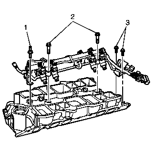
- Install the fuel rail assembly in intake manifold. Tilt the rail assembly to install the injectors.
- Install the fuel rail stud (1) and bolts (2, 3).
- Connect the fuel injector regulator vacuum hose connection to the intake manifold fitting.
- Apply lubricant GM P/N 9985770 or equivalent to the MAP sensor seal.
- Install the MAP sensor.
- Install the MAP sensor retainer.
- Install the MAP sensor retainer nut.
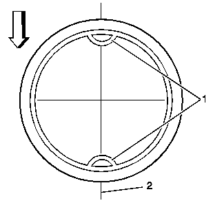
- Align the oil fill tube notches (1) parallel to the center line of the crankshaft (2).
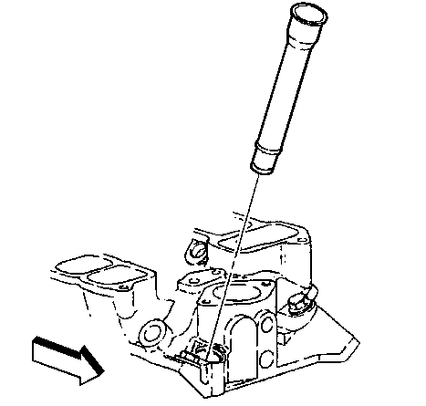
- Apply a 6.0 mm (0.240 in) bead of sealant GM P/N 9985409 or equivalent to the intake manifold end of the oil fill tube.
- Install the oil fill tube, if removed.
Notice: Use the correct fastener in the correct location. Replacement fasteners must be the correct part number for that application. Fasteners requiring replacement or fasteners requiring the use of thread locking compound or sealant are identified in the service procedure. Do not use paints, lubricants, or corrosion inhibitors on fasteners or fastener joint surfaces unless specified. These coatings affect fastener torque and joint clamping force and may damage the fastener. Use the correct tightening sequence and specifications when installing fasteners in order to avoid damage to parts and systems.
Tighten
Tighten the ECT sensor to 20 N·m (15 lb ft).
Tighten
Tighten the thermostat bypass hose fitting to 15 N·m (11 lb ft).
Tighten
Tighten the coolant outlet housing bolts to 40 N·m (30 lb ft).
Important: Lubricate the injector O-ring seals with clean engine oil and install onto the spray tip end of each injector.
Tighten
| • | Tighten the fuel rail stud (1) to 25 N·m (18 lb ft). |
| • | Tighten the fuel rail bolts (2, 3) to 10 N·m (89 lb in). |
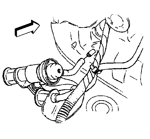
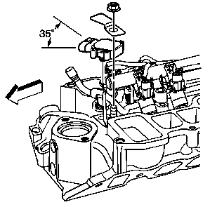
Important: Position the MAP sensor correctly in order to ensure proper clearance for the wiring harness connector.
Tighten
Tighten the MAP sensor retainer nut to 25 N·m (18 lb ft).
Intake Manifold Assemble Upper
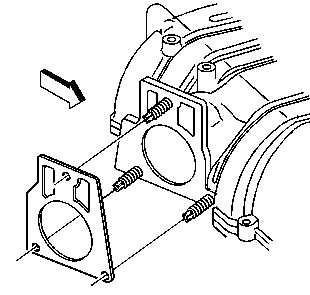
- Install the throttle body studs, if removed.
- Install the NEW throttle body gasket.
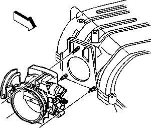
- Install the throttle body.
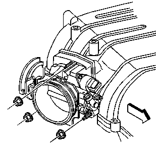
- Install the throttle body nuts.
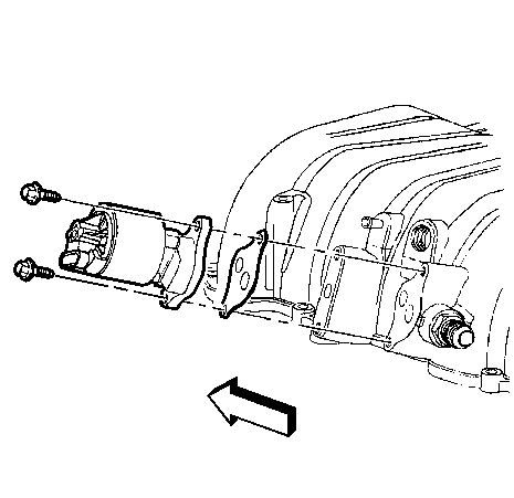
- Install the NEW EGR gasket
- Install the EGR valve.
- Install the EGR valve bolts.
- Tighten the EGR valve bolts a first pass to 10 N·m (89 lb in).
- Tighten the EGR valve bolts a final pass to 22 N·m (16 lb ft).
- Install the EVAP purge solenoid valve.
- Install the EVAP purge solenoid valve bolts.
- Install the secondary air injection check valve bracket (RPO K19 only), if removed .
- Install the secondary air injection check valve bracket stud.
- Install the secondary air injection check valve bracket stud (without RPO K19), if removed.
- Install the ECT wiring harness connector bracket, if removed.
- Install the ECT wiring harness connector bracket bolt.
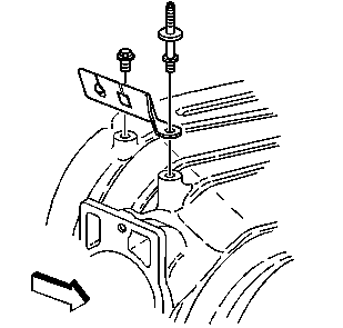
- Install the accelerator control cable bracket, if removed.
- Install the accelerator control cable bracket bolt and stud.
Notice: Use the correct fastener in the correct location. Replacement fasteners must be the correct part number for that application. Fasteners requiring replacement or fasteners requiring the use of thread locking compound or sealant are identified in the service procedure. Do not use paints, lubricants, or corrosion inhibitors on fasteners or fastener joint surfaces unless specified. These coatings affect fastener torque and joint clamping force and may damage the fastener. Use the correct tightening sequence and specifications when installing fasteners in order to avoid damage to parts and systems.
Tighten
Tighten the throttle body studs to 12 N·m (106 lb in).
Tighten
Tighten the throttle body nuts to 10 N·m (89 lb in).
Tighten
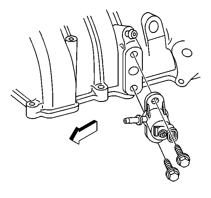
Tighten
Tighten the EVAP purge solenoid valve bolts to 12 N·m (106 lb in).
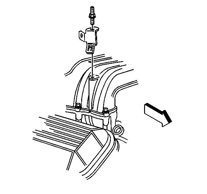
Tighten
Tighten the secondary air injection check valve bracket stud to 25 N·m
(18 lb ft).
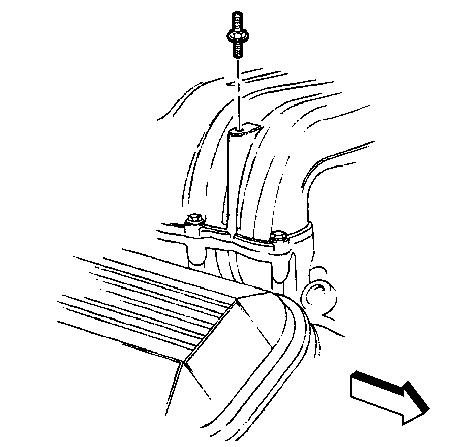
Tighten
Tighten the secondary air injection check valve bracket stud to 25 N·m
(18 lb ft).
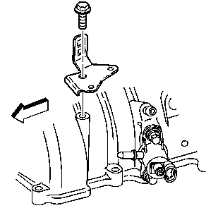
Tighten
Tighten the ECT wiring harness connector bracket bolt to 25 N·m
(18 lb ft).
Tighten
Tighten the accelerator control cable bracket bolt and stud to 25 N·m
(18 lb ft).
