Heater Hoses Replacement Inlet Hose - 5.0L, 5.7L, 7.4L
Removal Procedure
Tools Required
J 38723 Heater Line Quick Connector Separator
- Drain the engine coolant. Refer to Cooling System Draining and Filling in Engine Cooling.
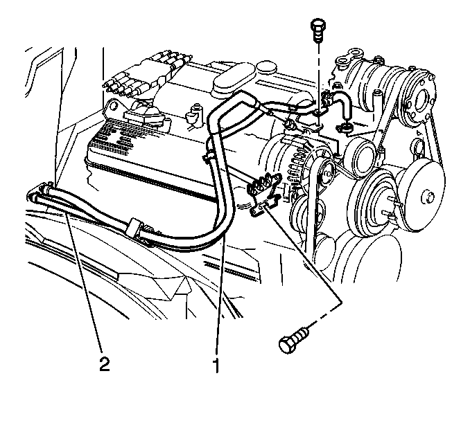
- Disconnect the inlet hose (1) from the generator bracket.
- Disconnect the inlet hose at the fender clip.
- Loosen the hose clamp at the heater core enough to slide the clamp away from the fitting on the inlet hose.
- Remove the hose clamp at the heater core, the water shut off valve, or the tee fitting.
- Disconnect the inlet hose from the heater core.
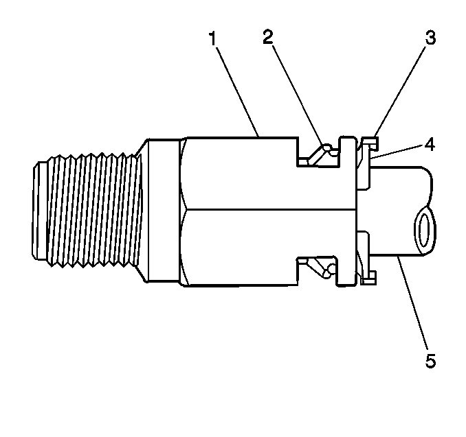
- Push the inlet hose (5) into the connector (1).
- Insert the J 38723 into the connector in order to release the locking tabs (2).
- Pull the retainer (4) and the inlet hose from the heater inlet connector.
- Inspect the O-ring sealing surface on the inlet hose.
- When replacing the heater inlet connector, remove the retainer from the hose.
- When replacing the inlet hose, but not the connector, complete the following steps:
- When reusing the inlet hose and the container, keep the retainer in place on the hose.


Discard the retainer.
| 12.1. | Remove the retainer from the inlet hose. |
| 12.2. | Reinsert the retainer in the connector. |
Installation Procedure
- Push the hose (5) into the connector (1) until the retainer tabs (3) lock.
- Pull back on the hose in order to verify for the proper engagement.
- Connect the inlet hose (1) to the heater core, the water shut off valve, or the tee fitting.
- Install the inlet hose clamp.
- Install the inlet hose mounting screw.
- Install the inlet hose to the fender clip.
- Add the engine coolant. Refer to Cooling System Draining and Filling in Engine Cooling.
- Inspect the system for leaks.


Notice: Use the correct fastener in the correct location. Replacement fasteners must be the correct part number for that application. Fasteners requiring replacement or fasteners requiring the use of thread locking compound or sealant are identified in the service procedure. Do not use paints, lubricants, or corrosion inhibitors on fasteners or fastener joint surfaces unless specified. These coatings affect fastener torque and joint clamping force and may damage the fastener. Use the correct tightening sequence and specifications when installing fasteners in order to avoid damage to parts and systems.
Tighten
Tighten the screw to 30 N·m (22 lb ft).
Heater Hoses Replacement Outlet Hose - 5.0L, 5.7L
Removal Procedure
- Drain the engine coolant. Refer to Cooling System Draining and Filling in Engine Cooling.
- Remove the outlet hose (2) from the fender clip.
- Remove the outlet hose clamp from the following components:
- Disconnect the outlet hose from the heater core.
- Remove the outlet hose mounting screw.
- Remove the outlet hose from the generator bracket.
- Remove the outlet hose clamp from the water pump.
- Disconnect the outlet hose from the water pump.

| • | heater core |
| • | water shut off valve |
| • | tee fitting |
Installation Procedure
- Connect the outlet hose (2) to the water pump.
- Install the outlet hose clamp to the water pump.
- Install the outlet hose to the generator bracket.
- Install the generator bracket mounting screw.
- Connect the outlet hose to the heater core.
- Install the outlet hose clamp to the heater core.
- Install the outlet hose to the fender clip.
- Add the engine coolant. Refer to Cooling System Draining and Filling in Engine Cooling.
- Inspect the system for leaks.

Notice: Use the correct fastener in the correct location. Replacement fasteners must be the correct part number for that application. Fasteners requiring replacement or fasteners requiring the use of thread locking compound or sealant are identified in the service procedure. Do not use paints, lubricants, or corrosion inhibitors on fasteners or fastener joint surfaces unless specified. These coatings affect fastener torque and joint clamping force and may damage the fastener. Use the correct tightening sequence and specifications when installing fasteners in order to avoid damage to parts and systems.
Tighten
Tighten the screw to 30 N·m (22 lb ft).
Heater Hoses Replacement Outlet Hose - 7.4L
Removal Procedure
- Drain the engine coolant. Refer to Cooling System Draining and Filling in Engine Cooling.
- Remove the outlet hose clamps.
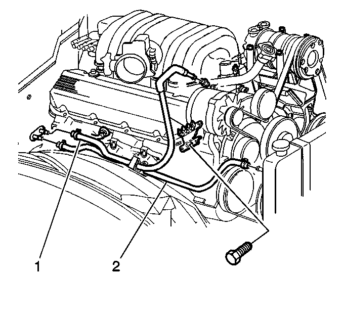
- Remove the outlet hose (2) from the fender clip.
- Disconnect the outlet hose from the heater core.
- Disconnect the outlet hose from the radiator.

Installation Procedure
- Connect the outlet hose (2) to the radiator.
- Connect the outlet hose to the heater core.
- Install the outlet hose to the fender clip.
- Install the hose clamps.
- Add the engine coolant. Refer to Cooling System Draining and Filling in Engine Cooling.
- Inspect the system for leaks.

Heater Hoses Replacement Inlet Hose - Diesel
Removal Procedure
Tools Required
J 38723 Heater Line Quick Connector Separator
- Drain the engine coolant. Refer to Cooling System Draining and Filling in Engine Cooling.
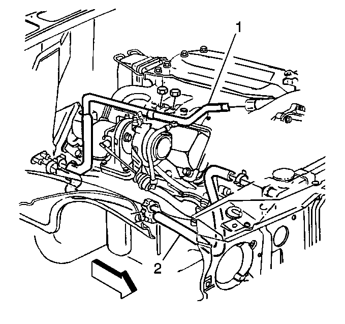
- Remove the inlet hose (1) from the generator bracket.
- Remove the inlet hose mounting nuts.
- Loosen the inlet hose clamp at the heater core enough in order to slip the clamp away from the fitting on the inlet hose.
- Remove the inlet hose clamp at the heater core.
- Disconnect the inlet hose from the heater core.
- Push the inlet hose (5) into the connector (1).
- Insert J 38723 into the connector in order to release the locking tabs (2).
- Pull the retainer (4) and the inlet hose from the heater inlet connector.
- Inspect the O-ring sealing surface on the inlet hose.
- When replacing the heater inlet connector, remove the retainer from the hose.
- When replacing the inlet hose, but not the connector, complete the following steps:
- When reusing the inlet hose and the container, keep the retainer in place on the hose.


Discard the retainer.
| 12.1. | Remove the retainer from the inlet hose. |
| 12.2. | Reinsert the retainer in the connector. |
Installation Procedure
- Push the inlet hose (5) into the connector (1) until the retainer tabs (3) lock.
- Pull back on the inlet hose in order to verify for the proper engagement.
- Connect the inlet hose (1) to the heater core.
- Install the inlet hose clamp (7).
- Install the inlet hose screw.
- Add the engine coolant. Refer to Cooling System Draining and Filling in Engine Cooling.
- Inspect the system for leaks.


Notice: Use the correct fastener in the correct location. Replacement fasteners must be the correct part number for that application. Fasteners requiring replacement or fasteners requiring the use of thread locking compound or sealant are identified in the service procedure. Do not use paints, lubricants, or corrosion inhibitors on fasteners or fastener joint surfaces unless specified. These coatings affect fastener torque and joint clamping force and may damage the fastener. Use the correct tightening sequence and specifications when installing fasteners in order to avoid damage to parts and systems.
Tighten
Tighten the screw to 30 N·m (22 lb ft).
Heater Hoses Replacement Outlet Hose - Diesel
Removal Procedure
- Drain the coolant. Refer to Cooling System Draining and Filling in Engine Cooling.
- Disconnect the outlet hose (2) from the radiator connection.
- Disconnect the outlet hose from the heater core connection.
- Remove the outlet hose from the outlet hose clip.
- Disconnect the outlet hose from the engine.
- Remove the hose clamps from the outlet hose.

Installation Procedure
- Install the hose clamps to the outlet hose (2).
- Connect the outlet hose to the engine.
- Connect the outlet hose to the radiator connection.
- Connect the outlet hose to the heater core connection.
- Install the outlet hose to the outlet hose clip.
- Add the engine coolant. Refer to Cooling System Draining and Filling in Engine Cooling.
- Inspect the system for leaks.

