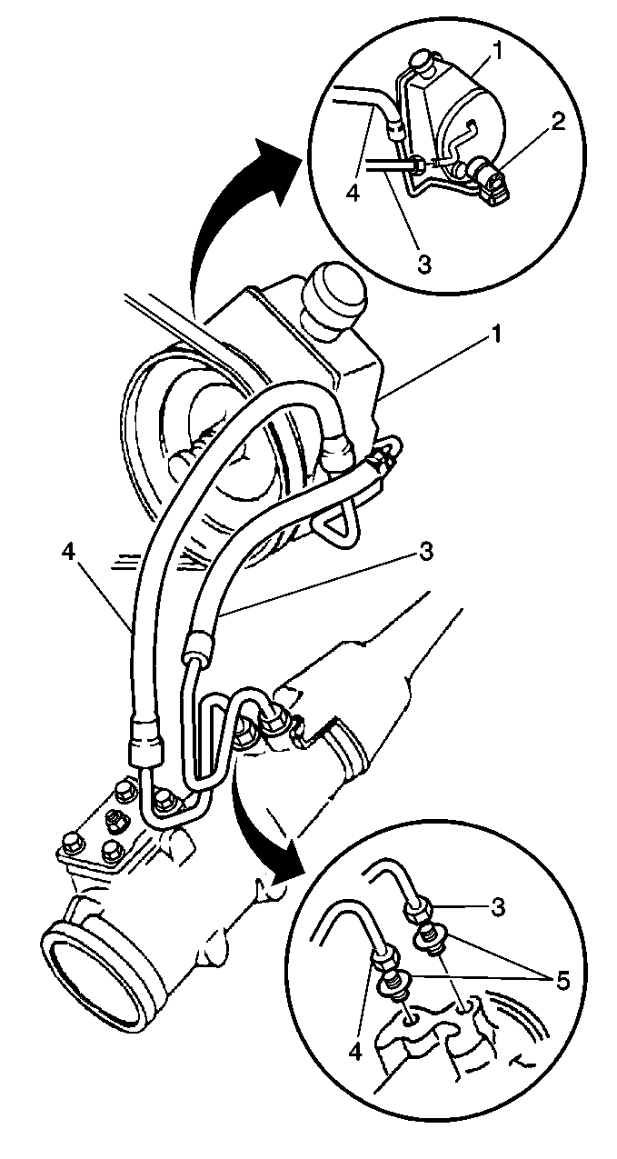
Power Steering Gear Inlet Hose With Vacuum Brake Booster
Notice: Do not start the vehicle with any power steering gear inlet or outlet hoses disconnected. When disconnected, plug or cap all openings of components. Failure to do so could result in contamination or loss of power steering fluid and damage to the system.
Notice: The inlet and outlet hoses must not be twisted during installation. Do not bend or distort the inlet or outlet hoses to make installation easier. Failure to follow these procedures could result in component damage.
Removal Procedure
- Install a drain pan under the vehicle.
- Siphon the power steering fluid from the reservoir to prevent excessive spillage.
- Remove the power steering gear inlet hose (4) from the power steering gear.
- Remove the power steering gear inlet hose (4) from the power steering pump.
- Remove the power steering gear inlet hose from the vehicle.
Installation Procedure
- Route the hose in the same position the hose occupied prior to removal.
- Install the power steering gear inlet hose (4) to the power steering pump.
- Install the power steering gear inlet hose (4) to the power steering gear.
- Remove the drain pan from under the vehicle.
- Bleed the power steering system. Refer to Power Steering System Bleeding .
Notice: Use the correct fastener in the correct location. Replacement fasteners must be the correct part number for that application. Fasteners requiring replacement or fasteners requiring the use of thread locking compound or sealant are identified in the service procedure. Do not use paints, lubricants, or corrosion inhibitors on fasteners or fastener joint surfaces unless specified. These coatings affect fastener torque and joint clamping force and may damage the fastener. Use the correct tightening sequence and specifications when installing fasteners in order to avoid damage to parts and systems.
Tighten
Tighten the power steering gear inlet hose (4) at the power steering
pump to 27 N·m (20 lb ft).
Tighten
Tighten the power steering gear inlet hose (4) at the power steering
gear to 27 N·m (20 lb ft).
Power Steering Gear Outlet Hose With Vacuum Brake Booster
Notice: Do not start the vehicle with any power steering gear inlet or outlet hoses disconnected. When disconnected, plug or cap all openings of components. Failure to do so could result in contamination or loss of power steering fluid and damage to the system.
Notice: The inlet and outlet hoses must not be twisted during installation. Do not bend or distort the inlet or outlet hoses to make installation easier. Failure to follow these procedures could result in component damage.
Removal Procedure
- Install a drain pan under the vehicle.
- Siphon the power steering fluid from the reservoir to prevent excessive spillage.
- Remove the power steering gear outlet hose (3) from the power steering pump.
- Remove the power steering gear outlet hose (3) from the power steering gear.
- Remove the power steering gear outlet hose from the vehicle.
Installation Procedure
- Route the hose in the same position the hose occupied prior to removal.
- Install the power steering gear outlet hose (3) to the power steering gear.
- Position the clamp on the pump end of the power steering gear outlet hose.
- Install the power steering gear outlet hose (3) to the power steering pump.
- Remove the drain pan from under the vehicle.
- Bleed the power steering system. Refer to Power Steering System Bleeding .
Notice: Use the correct fastener in the correct location. Replacement fasteners must be the correct part number for that application. Fasteners requiring replacement or fasteners requiring the use of thread locking compound or sealant are identified in the service procedure. Do not use paints, lubricants, or corrosion inhibitors on fasteners or fastener joint surfaces unless specified. These coatings affect fastener torque and joint clamping force and may damage the fastener. Use the correct tightening sequence and specifications when installing fasteners in order to avoid damage to parts and systems.
Tighten
Tighten the power steering gear outlet hose (3) at the power steering
gear to 27 N·m (20 lb ft).
Tighten
Tighten the clamp on the power steering gear outlet hose. Fully crimp
the clamp until zero gap between both halves is achieved prior to springback.
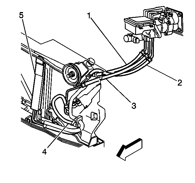
Power Steering Gear Inlet Hose With Hydraulic Brake Booster
Notice: Do not start the vehicle with any power steering gear inlet or outlet hoses disconnected. When disconnected, plug or cap all openings of components. Failure to do so could result in contamination or loss of power steering fluid and damage to the system.
Notice: The inlet and outlet hoses must not be twisted during installation. Do not bend or distort the inlet or outlet hoses to make installation easier. Failure to follow these procedures could result in component damage.
Removal Procedure
- Install a drain pan under the vehicle.
- Siphon the power steering fluid from the reservoir to prevent excessive spillage.
- Remove the power steering gear inlet hose (3) from the hydraulic brake booster.
- Remove the power steering gear inlet hose (3) from the power steering gear.
- Remove the power steering gear inlet hose from the vehicle.
Installation Procedure
- Route the hose in the same position the hose occupied prior to removal.
- Install the power steering gear inlet hose (3) to the hydraulic brake booster.
- Install the power steering gear inlet hose (3) to the power steering gear.
- Remove the drain pan from under the vehicle.
- Bleed the power steering system. Refer to Power Steering System Bleeding .
Notice: Use the correct fastener in the correct location. Replacement fasteners must be the correct part number for that application. Fasteners requiring replacement or fasteners requiring the use of thread locking compound or sealant are identified in the service procedure. Do not use paints, lubricants, or corrosion inhibitors on fasteners or fastener joint surfaces unless specified. These coatings affect fastener torque and joint clamping force and may damage the fastener. Use the correct tightening sequence and specifications when installing fasteners in order to avoid damage to parts and systems.
Tighten
Tighten the power steering gear inlet hose (3) at the hydraulic brake
booster to 27 N·m (20 lb ft).
Tighten
Tighten the power steering gear inlet hose (3) at the power steering
gear to 27 N·m (20 lb ft).
Hydraulic Brake Booster Inlet Hose
Notice: Do not start the vehicle with any power steering gear inlet or outlet hoses disconnected. When disconnected, plug or cap all openings of components. Failure to do so could result in contamination or loss of power steering fluid and damage to the system.
Notice: The inlet and outlet hoses must not be twisted during installation. Do not bend or distort the inlet or outlet hoses to make installation easier. Failure to follow these procedures could result in component damage.
Removal Procedure
- Install a drain pan under the vehicle.
- Siphon the power steering fluid from the reservoir to prevent excessive spillage.
- Remove the hydraulic brake booster inlet hose (2) from the power steering pump.
- Remove the hydraulic brake booster inlet hose (2) from the hydraulic brake booster.
- Remove the hydraulic brake booster inlet hose from the vehicle.
Installation Procedure
- Route the hose in the same position the hose occupied prior to removal.
- Install the hydraulic brake booster inlet hose (3) to the hydraulic brake booster.
- Install the hydraulic brake booster inlet hose (2) to the power steering pump.
- Remove the drain pan from under the vehicle.
- Bleed the power steering system. Refer to Power Steering System Bleeding .
Notice: Use the correct fastener in the correct location. Replacement fasteners must be the correct part number for that application. Fasteners requiring replacement or fasteners requiring the use of thread locking compound or sealant are identified in the service procedure. Do not use paints, lubricants, or corrosion inhibitors on fasteners or fastener joint surfaces unless specified. These coatings affect fastener torque and joint clamping force and may damage the fastener. Use the correct tightening sequence and specifications when installing fasteners in order to avoid damage to parts and systems.
Tighten
Tighten the hydraulic brake booster inlet hose (2) at the hydraulic
brake booster to 27 N·m (20 lb ft).
Tighten
Tighten the hydraulic brake booster inlet hose (2) at the power steering
pump to 27 N·m (20 lb ft).
Hydraulic Brake Booster Outlet Hose
Notice: Do not start the vehicle with any power steering gear inlet or outlet hoses disconnected. When disconnected, plug or cap all openings of components. Failure to do so could result in contamination or loss of power steering fluid and damage to the system.
Notice: The inlet and outlet hoses must not be twisted during installation. Do not bend or distort the inlet or outlet hoses to make installation easier. Failure to follow these procedures could result in component damage.
Removal Procedure
- Install a drain pan under the vehicle.
- Siphon the power steering fluid from the reservoir to prevent excessive spillage.
- Remove the hydraulic brake booster outlet hose (1) from the power steering pump.
- Remove the hydraulic brake booster outlet hose (1) from the power steering gear.
- Remove the hydraulic brake booster outlet hose from the vehicle.
Installation Procedure
- Route the hose in the same position the hose occupied prior to removal.
- Install the hydraulic brake booster outlet hose (1) to the power steering gear.
- Position the clamp on the pump end of the hydraulic brake booster outlet hose.
- Install the hydraulic brake booster outlet hose (1) to the power steering pump.
- Remove the drain pan from under the vehicle.
- Bleed the power steering system. Refer to Power Steering System Bleeding .
Notice: Use the correct fastener in the correct location. Replacement fasteners must be the correct part number for that application. Fasteners requiring replacement or fasteners requiring the use of thread locking compound or sealant are identified in the service procedure. Do not use paints, lubricants, or corrosion inhibitors on fasteners or fastener joint surfaces unless specified. These coatings affect fastener torque and joint clamping force and may damage the fastener. Use the correct tightening sequence and specifications when installing fasteners in order to avoid damage to parts and systems.
Tighten
Tighten the hydraulic brake booster outlet hose (1) at the power steering
gear to 27 N·m (20 lb ft).
Tighten
Tighten the clamp on the hydraulic brake booster outlet hose. Fully
crimp the clamp until zero gap between both halves is achieved prior to springback.
