DTC P0719 Brake Switch Circuit Low Input Gas
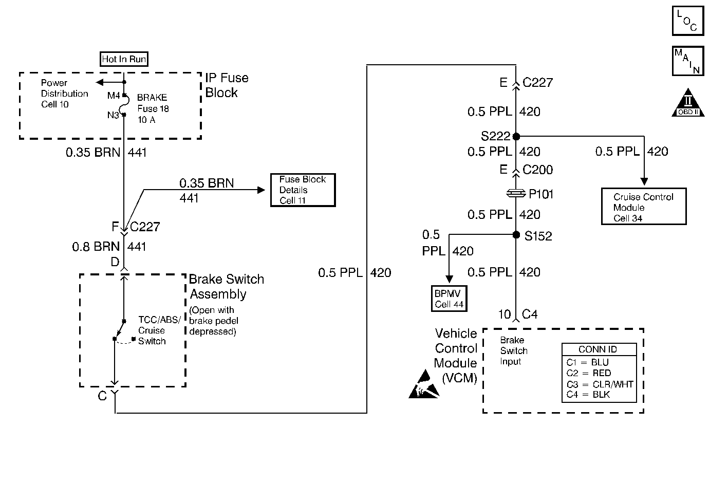
Circuit Description
The TCC/Stoplamp switch indicates the brake pedal status. The normally-closed TCC/Stoplamp switch supplies a B+ signal on circuit 420 to the vehicle control module (VCM). The signal voltage circuit opens when the brakes are applied.
If the VCM detects an open TCC/Stoplamp switch circuit during accelerations, then DTC P0719 sets. DTC P0719 is a type D DTC.
Conditions for Running the DTC
| • | No OSS DTC P0502 or DTC P0503. |
| • | The following sequence of events occurs: |
| 1. | The vehicle speed is less than 8 km/h (5 mph). |
| 2. | Then the vehicle speed is 8-40 km/h (5-25 mph) for 3.1 seconds. |
| 3. | Then the vehicle speed is greater than 40 km/h (25 mph) for 6 seconds. |
Conditions for Setting the DTC
| • | All conditions are met for 8 occurrence. |
| • | The VCM detects an open TCC/Stoplamp switch/circuit (0 volts). |
| • | The brake switch is ON for greater than 900 seconds (15 minutes). |
Action Taken When the DTC Sets
| • | The VCM does not illuminate the malfunction indicator lamp (MIL). |
| • | For TCC scheduling, the VCM disregards the brake switch state if the TP sensor is greater than 1% and the vehicle speed is greater than 20 MPH. |
| • | The VCM stores DTC P0719 in VCM history. |
Conditions for Clearing the DTC
| • | A scan tool clears the DTC from VCM history. |
| • | The VCM clears the DTC from VCM history if the vehicle completes 40 warm-up cycles without a non-emission-related diagnostic fault occurring. |
| • | The VCM cancels the DTC default actions when the fault no longer exists and the ignition switch is OFF long enough in order to power down the VCM. |
Diagnostic Aids
| • | Inspect the wiring at the VCM, the TCC/Stoplamp switch and all other circuit connecting points for the following conditions: |
| - | A backed out terminal |
| - | A damaged terminal |
| - | Reduced terminal tension |
| - | A chafed wire |
| - | A broken wire inside the insulation |
| - | Moisture intrusion |
| - | Corrosion |
| • | When diagnosing for an intermittent short or open, massage the wiring harness while watching the test equipment for a change. |
| • | Ask about the customer's driving habits and any unusual driving conditions he or she might have, such as stop and go traffic or expressway driving. |
| • | Inspect the brake switch for proper mounting and adjustment. |
| • | Inspect for the most current calibration ID and the latest bulletins. |
| • | First diagnose and clear any engine DTCs or TP sensor codes that are present. Then inspect for any transmission DTCs that may have reset. |
Test Description
The numbers below refer to the step numbers on the diagnostic table.
-
This step tests for TCC/Stoplamp switch voltage to the VCM connector.
-
This step isolates the TCC/Stoplamp switch as a source for setting the DTC.
-
This step tests for a short to ground in circuit 441 (ignition voltage) to the TCC/Stoplamp switch.
-
This step tests for a short to ground in circuit 420, from the TCC/Stoplamp switch to the VCM.
-
This step isolates the VCM as a source for causing the fuse to open.
Step | Action | Value(s) | Yes | No | ||||||
|---|---|---|---|---|---|---|---|---|---|---|
1 | Was the Powertrain On-Board Diagnostic (OBD) System Check performed? | -- | Go to Powertrain On Board Diagnostic (OBD) System Check (5.7L) or Powertrain On Board Diagnostic (OBD) System Check (7.4L) | |||||||
2 |
Important: Before clearing the DTCs, use the scan tool in order to record the Failure Records. Using the Clear Info function erases the Failure Records from the VCM. Does the Scan Tool TCC/Stoplamp Switch indicate CLOSED, when the brake pedal is not applied? | -- | Go to Diagnostic Aids | |||||||
3 |
Refer to General Electrical Diagnosis in Wiring Systems. Is the fuse open? | -- | ||||||||
Is the test lamp on? | -- | |||||||||
5 |
Is B+ voltage indicated? | 10-13 volts | ||||||||
6 |
Important: The condition that affects this circuit may exist in other connecting branches of the circuit. Refer to Power Distribution Schematics in Wiring Systems for complete circuit distribution. Inspect circuit 441 (BRN) for an open. Was the condition corrected? | -- | -- | |||||||
Is the test lamp on? | -- | |||||||||
8 |
Important: The condition that affects this circuit may exist in other connecting branches of the circuit. Refer to Power Distribution Schematics in Wiring Systems for complete circuit distribution. Inspect circuit 420 (PPL) for an open. Was the condition corrected? | -- | -- | |||||||
9 | Replace the TCC/Stoplamp switch. Refer to Stop Lamp Switch Replacement in Hydraulic Brakes. Is the replacement complete? | -- | -- | |||||||
Does the fuse open with the brake pedal applied? | -- | |||||||||
11 |
Important: The condition that affects this circuit may exist in other connecting branches of the circuit. Refer to Power Distribution Schematics in Wiring Systems for complete circuit distribution. Inspect circuit 441 (BRN) for a short to ground. Was the condition corrected? | -- | -- | |||||||
With the key in the RUN position, release the brake pedal. Does the fuse open when the brake pedal is released? | -- | Go to Diagnostic Aids | ||||||||
Does the fuse open? | -- | |||||||||
14 |
Important: The condition that affects this circuit may exist in other connecting branches of the circuit. Refer to Power Distribution Schematics in Wiring Systems for complete circuit distribution. Inspect circuit 420 (PPL) for a short to ground. Was the condition corrected? | -- | -- | |||||||
15 | Inspect the VCM terminals for corrosion or reduced terminal tension. Was a shorted condition found? | -- | ||||||||
16 | Replace the VCM. Refer to VCM Replacement/Programming with KS calibration prom. Is the replacement complete? | -- | -- | |||||||
17 | Perform the following procedure in order to verify the repair:
Does the TCC Brake Sw. indicate CLOSED when the brake pedal is not applied, then indicate OPEN when the brake pedal is applied? | -- | System OK |
DTC P0719 Brake Switch Circuit Low Input Diesel
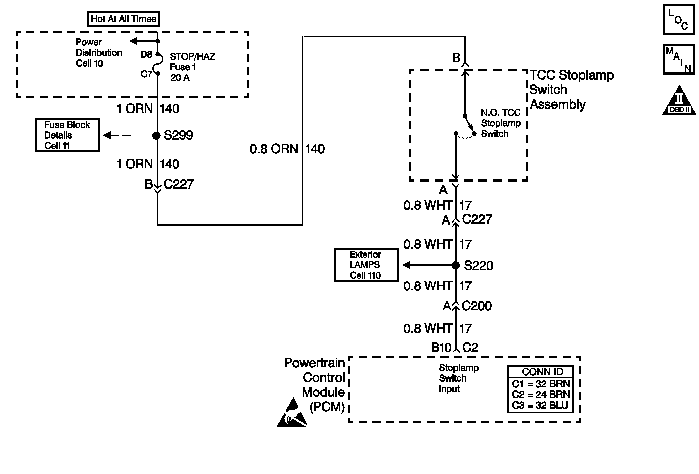
Circuit Description
The normally open TCC/Stoplamp switch indicates brake pedal status to the powertrain control module (PCM). Applying the brake pedal closes the switch, supplying voltage to the PCM. Releasing the brake pedal interrupts voltage to the PCM.
If the PCM detects an open TCC/Stoplamp switch (stuck OFF) during decelerations, then DTC P0719 sets. DTC P0719 is a type D DTC.
Conditions for Running the DTC
| • | The system voltage is 8.0-18.0 volts. |
| • | The engine speed is greater than 475 RPM for greater than 7 seconds. |
| • | No OSS DTCs P0722 or P0723. |
| • | The following sequence of events occur: |
| - | The vehicle speed is greater than 44 km/h (27 mph) for 7 seconds. |
| - | The vehicle speed is 8-20 km/h (5-12 mph) for greater than 2 seconds, but less than 11 seconds. |
| - | The vehicle speed is less than 8 km/h (5 mph). |
Conditions for Setting the DTC
| • | All the conditions for running the DTC are met for ten occurrences. |
| • | The PCM detects an open TCC/Stoplamp switch circuit (0 volts). |
Action Taken When the DTC Sets
| • | The PCM does not illuminate the malfunction indicator lamp (MIL). |
| • | The PCM stores DTC P0719 in PCM history. |
Conditions for Clearing the DTC
| • | A scan tool clears the DTC from PCM history. |
| • | The PCM clears the DTC from PCM history if the vehicle completes 40 consecutive warm-up cycles without a non-emission-related diagnostic fault occurring. |
| • | The PCM cancels the DTC default actions when the fault no longer exists and the ignition switch is OFF long enough in order to power down the PCM. |
Diagnostic Aids
| • | Inspect the wiring at the PCM, the TCC/Stoplamp switch connector and all other circuit connecting points for the following conditions: |
| - | A backed out terminal |
| - | A damaged terminal |
| - | Reduced terminal tension |
| - | A chafed wire |
| - | A broken wire inside the insulation |
| - | Moisture intrusion |
| - | Corrosion |
| • | When diagnosing for an intermittent short or open, massage the wiring harness while watching the test equipment for a change. |
| • | Ask about the customer's driving habits and any unusual driving conditions he or she might have, such as stop and go traffic or expressway driving. |
| • | Inspect the TCC/Stoplamp switch for proper mounting and adjustment. |
| • | First diagnose and clear any engine DTCs codes that are present. Then inspect for any transmission DTCs that may have reset. |
Test Description
The numbers below refer to the step numbers on the diagnostic table.
-
This step isolates the TCC/Stoplamp switch as a source for setting the DTC.
-
This step tests for a short to ground between the fuse and the TCC/Stoplamp switch.
-
This step tests for a short to ground in circuit 17.
-
This step removes the PCM from circuit 17 as the source of a short to ground.
Step | Action | Value(s) | Yes | No | ||||||
|---|---|---|---|---|---|---|---|---|---|---|
1 | Was the Powertrain On-Board Diagnostic (OBD) System Check performed? | -- | ||||||||
2 |
Important: Before clearing the DTCs, use the scan tool in order to record the Freeze Frame and Failure Records. Using the Clear Info function erases the Failure Records from the PCM. Is the test lamp ON? | -- | ||||||||
Install a fused jumper wire from terminal B to terminal A of the TCC/Stoplamp switch connector. Did the scan tool TCC/Brake switch status change from OPEN to CLOSED? | -- | |||||||||
4 |
Refer to General Electrical Diagnosis in Wiring Systems. Is the fuse open? | -- | ||||||||
Replace the Stop/Hazard fuse. Does the replacement fuse open immediately? | -- | |||||||||
6 | Inspect circuit 140 (ORN) for a short to ground. Refer to General Electrical Diagnosis in Wiring Systems. Was the condition corrected? | -- | -- | |||||||
Does the fuse open immediately? | -- | Go to Diagnostic Aids. | ||||||||
| -- | |||||||||
9 | Inspect circuit 17 (WHT) for a short to ground. Refer to General Electrical Diagnosis in Wiring Systems. Was the condition corrected? | -- | -- | |||||||
10 | Replace the TCC/Stoplamp switch. Refer to Stop Lamp Switch Replacement in Hydraulic Brakes. Is the replacement complete? | -- | -- | |||||||
11 | Inspect circuit 140 (ORN) for an open. Refer to General Electrical Diagnosis in Wiring Systems. Was the condition corrected? | -- | -- | |||||||
12 | Inspect circuit 17 (WHT) for an open. Refer to General Electrical Diagnosis in Wiring Systems. Was the condition found? | -- | ||||||||
13 | Inspect the PCM pins, the connector terminals, and the wiring for corrosion or shorting together. Was the condition found? | -- | ||||||||
14 | Replace the PCM. Refer to Powertrain Control Module Replacement/Programming in Engine Controls. Is the replacement complete? | -- | -- | |||||||
15 | Perform the following procedure in order to verify the repair:
Has the test run and passed? | -- | System OK |
