Circuit Description
The Class II Serial Data Circuit is used communicate between systems.
Each system connected to the Class II Serial Data line is assigned its own
recognition code (address). This code is used to identify which module
or systems are communicating. The Node Alive or State of Health (SOH)
messages are broadcast on the bus every 2 seconds. If a module
is monitoring Node Alive messages for that module, it will reset its
5 second timer for that particular module. Any system that communicate
properly will also store the appropriate communication Diagnostic Trouble
Codes (DTCs) that are assigned to the system(s) it could not communicate
with.
Conditions for Setting the DTC
| • | The Vehicle Control Module (VCM)/Powertrain Control Module (PCM)
has established communications, received Node Alive/SOH messages, during this
ignition cycle with the Electronic brake Control Module (EBCM). |
| • | The VCM/PCM cannot re-establish communications, no Node Alive/SOH
messages received, with the EBCM for 5 seconds. |
Action Taken When the DTC Sets
| • | A DTC U1041 is stored in the VCM/PCM memory. |
| • | The VCM/PCM will not illuminate the Malfunction Indicator Lamp. |
Conditions for Clearing the MIL/DTC
| • | This DTC requires an ignition cycle in order to change from Current
to History. |
| • | The VCM/PCM receives a Node Alive/SOH message back from the EBCM. |
| • | A history DTC will clear after 40 consecutive ignition cycles
if the condition for the malfunction is no longer present. |
| • | The DTCs can be cleared using a scan tool. |
Diagnostic Aids
| | Important: Do not clear the DTCs unless directed by a diagnostic procedure. Clearing
the DTCs will also clear valuable Freeze Frame and Failure Records information.
|
| • | Inspect for published service bulletins relating to the exhibited symptoms
or component operation. |
| • | Inspect all related wiring and connections including the connections
at the VCM/PCM and the ATC Control Module. These connections may cause an
intermittent malfunction. |
| • | Thoroughly inspect any circuit that can cause an intermittent
complaint for the following items: |
| - | Improper mating of connectors |
| - | Improper mating of connectors |
| - | Improperly formed or damaged terminals |
| - | Poor terminal to wiring connections |
| - | Physical damage to the wiring harness |
| - | Corroded terminal to connections |
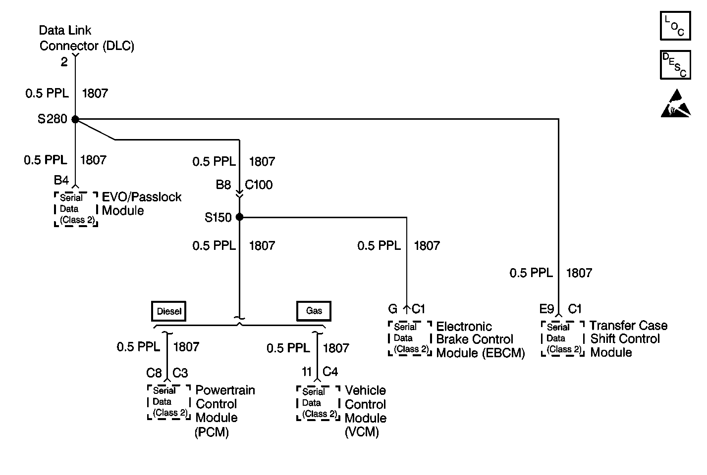
| • | All of the modules or systems connected to the Class II Serial
Data line will not communicate properly if the following conditions are present: |
| - | The Class II Serial Data line is shorted up to ground |
| - | The Class II Serial Data line is shorted to voltage |
| - | The systems or modules that are capable of storing loss of communications
DTC's (DTC's with the letter U as a prefix) will have these codes in their
memory. If a DTC U1041 is stored in the VCM/PCM memory, inspect for the
same DTC stored in the Active Transfer Case (ATC) Control Module. The
ATC Control Module also monitors the Node Alive/SOH message from the
Electronic Brake Control Module (EBCM). If the ATC Control Module
has a DTC U1041 stored, inspect the for an open in the Class II Serial
Data circuit between the VCM and the EBCM. |
| - | Use the scan tool in order to perform the following functions: |
| - | Monitor the Class II Serial Data circuit for Node Alive/SOH messages |
| - | Monitor the loss of communications DTC's (DTC's with the letter
U as a prefix) |
| - | Clear the loss of communication DTCs |
| • | The scan tool's Diagnostic Circuit Check status of Active indicates
that the module is communicating with the scan tool. An inactive status indicates
that the module previously communicated with the scan tool, but is not
communicating currently. If a module is not listed at all, the module
never successfully established communications with the scan tool. Refer
to
Diagnostic System Check - Data Link Communications
for the complete Class II data link diagnosis to determine
if there are any unlisted modules. |
Test Description
The number(s) below refer to the step number(s) on the diagnostic table.
-
The Automatic
Transfer Case System Check (Automatic Four Wheel Drive) will test the scan
tool's ability to communicate with the Automatic Transfer Case Control
Module (ATCM), Electronic Brake Control Module (EBCM),
and the Powertrain Control Module (PCM) or the Vehicle Control
Module (VCM). If communications are unable to be established with
the EBCM, a CURRENT fault exists, refer to
Diagnostic System Check - Data Link Communications
. This fault could
be caused by a faulty power or ground circuit to the EBCM, a faulty EBCM
or a faulty CKT 1807 (PPL).
-
If a HISTORY U1041 DTC is stored, this indicates the
communication circuits are OK and an intermittent condition exists. Refer
to
Diagnostic System Check - Data Link Communications
.
