For 1990-2009 cars only
- Disconnect the antenna from the extension cable.
- Plug in a test antenna.
- Ground the antenna to the vehicle chassis.
- Do not touch the antenna.
- Test the radio reception in an area away from electrical interference such as the following items:
- Tune into the high and the low ends of the radio dial on both FM and AM, checking for weak and strong station reception.
- If the reception is satisfactory, the problem exists in the antenna and/or the lead-in cable.
- If the reception is still poor, refer to Diagnosis earlier in this section.
| • | Tall buildings |
| • | Metal structures |
| • | Power lines |
| • | Florescent lighting |
| • | Power tools |
Testing for Good Ground of Antenna Mounting and Connections
| • | Poor grounds at the antenna mounting, or any other connection in the antenna/lead-in system, can result in seriously reduced radio performance. |
| • | A poor ground can be a reason for excess ignition noise on AM or bad audio. |
| • | Make sure that the lead-in connectors are free of dirt and corrosion, and are tightly fastened. |
| • | Possible ground loss or high-resistance ground points include the following steps: |
| - | Antenna upper mounting (loose screws, paint overspray, etc.) |
| - | Lead-in cable connector at the antenna, (loose or internally corroded) |
| - | Lead-in cable connector at the antenna (loose or internally corroded) |
| - | Quick connect connector (corroded) |
| - | Missing ground lead |
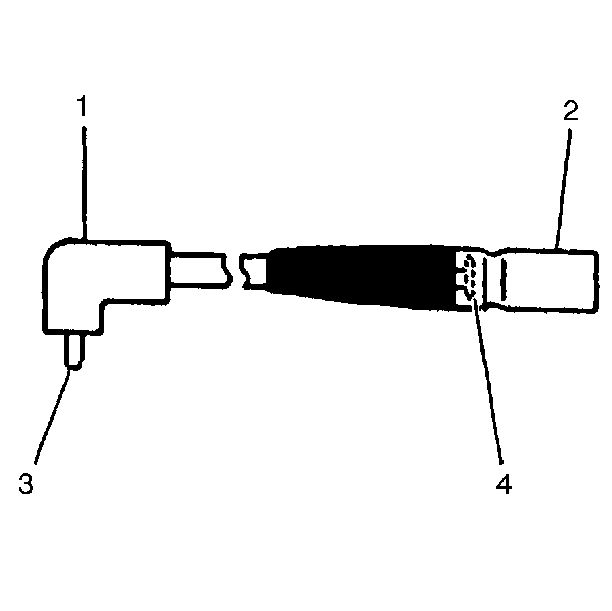
Measuring Resistance With a Digital Multimeter
Probes On | Indication (Ohms) |
|---|---|
3 and 4 | Less than 0.2 |
1 and 2 | Less than 0.2 |
2 and 4 | infinite |
1 and 3 | infinite |
1 and 4 | infinite |
2 and 3 | infinite |
*While measuring, wiggle lead - in tip and cable; the indications should not vary. | |
| • | Usually, a broken center conductor of the lead-in cable will result in no AM and weak FM radio stations. |
| • | In case of continued reception or noise complaints, always check the lead-in with an ohmmeter. |
| • | When checking resistance, wiggle the lead-in tip (3) and cable (4). |
- If the readings shown in the accompanying table are not obtained, some portion of the lead-in is intermittent.
- Replace the lead-in.
