Steering Knuckle Replacement RWD-All Except C3500HD
Removal Procedure
Tools Required
J 23742 Ball Joint
Separator
- Raise the front of the vehicle.
| • | Place safety stands under the front lift points. |
| • | Do not place floor stands under the lower control arms because
spring tension is needed to assist in breaking loose the ball joint studs. |
- Remove the tire and wheel assembly. Refer to
Tire and Wheel Removal and Installation
in Tires and Wheels.
Notice: Support the caliper with a piece of wire to prevent damage to the brake
line.
- Remove the brake caliper. Refer to
Brake Caliper Replacement
in Disc Brakes.
- Remove the hub/rotor assembly. Refer to
Front Wheel Hub, Bearing, and Seal Replacement
.
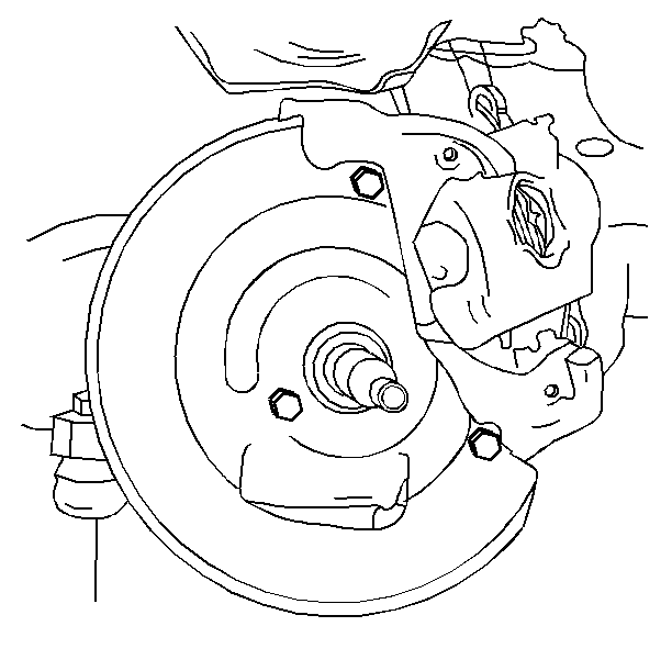
- Remove the three bolts
that attach the splash shield to the knuckle.
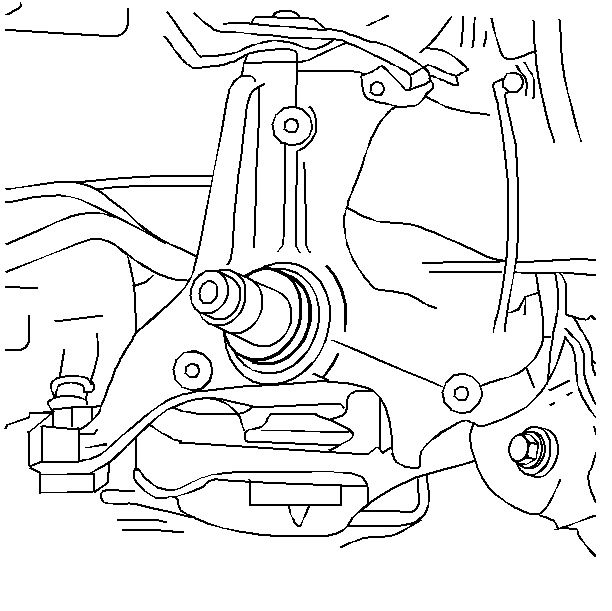
- Remove the knuckle seal
if the knuckle is to be replaced. Do not damage the knuckle seal.
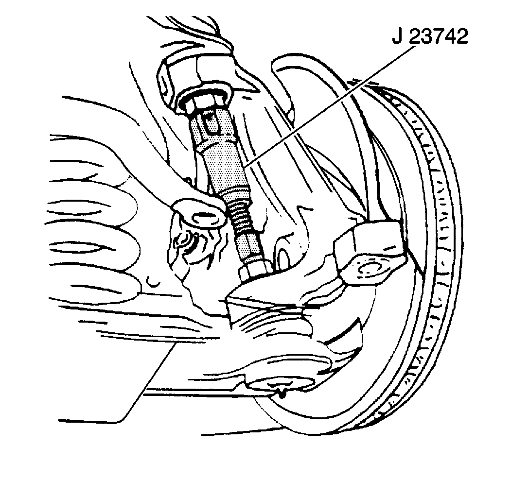
- Remove the lower ball
joint stud from the knuckle using the J 23742
.
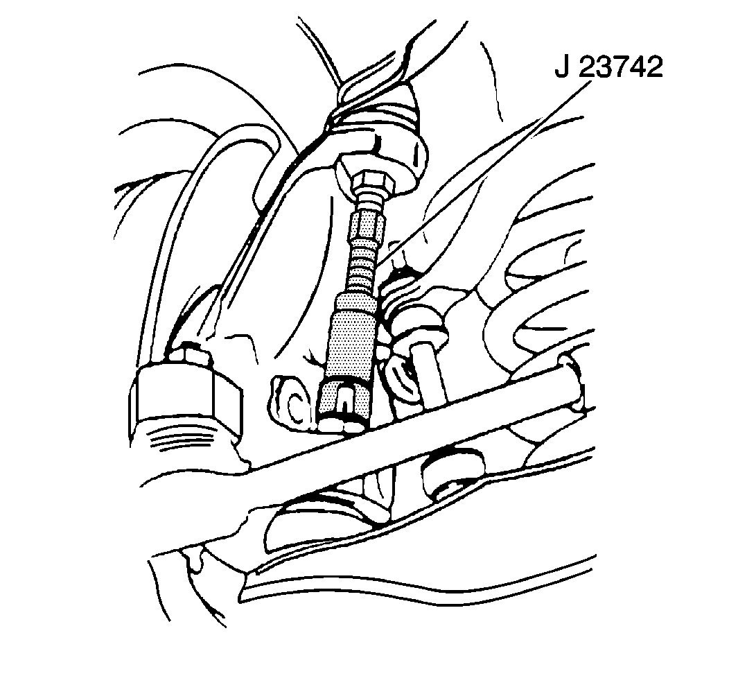
- Remove the upper ball
joint stud from the knuckle using the J 23742
.
Caution: Floor jack must remain under the lower control arm during
removal and installation to retain the lower control arm in position. Failure
to do so could result in personal injury.
- Position a floor jack under the lower control arm near the spring seat.
| • | Raise the jack until the jack just supports the lower control
arm. |
| • | Raise the upper control arm. Disengage the ball joint stud from
the knuckle. |
- Remove the knuckle from the lower ball joint stud.
| 10.1. | Clean the steering knuckle. |
| 10.2. | Inspect the steering knuckle tapered hole. If this tapered hole
is out-of-round, deformed, or damaged, replace the knuckle. |
Installation Procedure
- Install the upper ball joint into the knuckle. Refer to
Upper Control Arm Ball Joint Replacement
.
- Install the lower ball joint into the knuckle. Refer to
Lower Control Arm Ball Joint Replacement
.

- Install the knuckle seal.

- Install the splash shield
to the knuckle.
Notice: Use the correct fastener in the correct location. Replacement fasteners
must be the correct part number for that application. Fasteners requiring
replacement or fasteners requiring the use of thread locking compound or sealant
are identified in the service procedure. Do not use paints, lubricants, or
corrosion inhibitors on fasteners or fastener joint surfaces unless specified.
These coatings affect fastener torque and joint clamping force and may damage
the fastener. Use the correct tightening sequence and specifications when
installing fasteners in order to avoid damage to parts and systems.
- Install the bolts
to the splash shield.
Tighten
Tighten the bolts to 26 N·m (19 lb ft).
- Install the tie rod end into the knuckle.
- Install the hub/rotor assembly. Refer to
Front Wheel Hub, Bearing, and Seal Replacement
.
- Adjust the wheel bearings. Refer to
Wheel Bearing Adjustment
.
- Install the tire and wheel assembly. Refer to
Tire and Wheel Removal and Installation
in Tires and Wheels.
- Remove the floor stands.
- Lower the vehicle.
- Check the front wheel alignment. Refer to
Wheel Alignment Measurement
in Wheel Alignment.
Steering Knuckle Replacement C3500HD
Removal Procedure
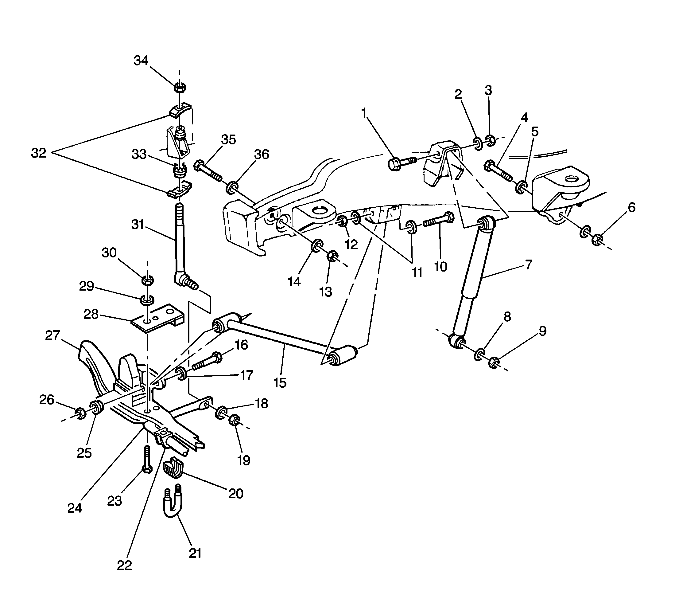
For steering arm, knuckle, and components, refer to
Shock Absorber, Axle Tie Rod, and Components (C3500HD)
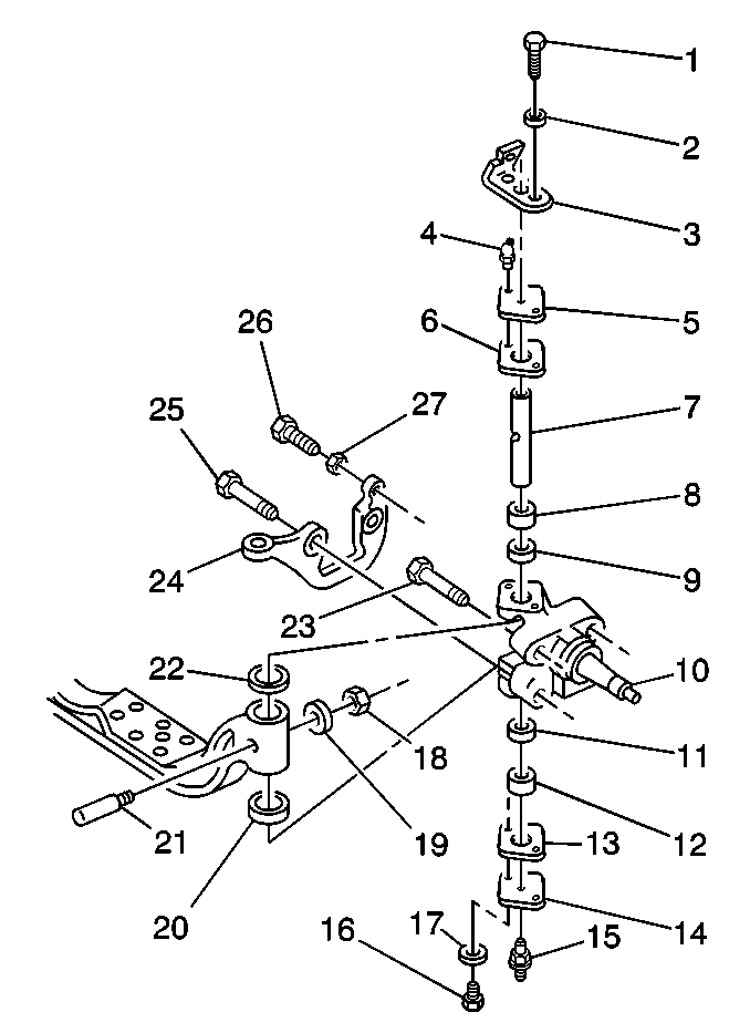
- Raise the vehicle. Support the vehicle with suitable safety stands. Refer to
Lifting and Jacking the Vehicle
in General Information.
- Remove the tire and wheel assembly. Refer to
Brake Caliper Replacement
in Tires and Wheels.
- Remove the brake caliper. Refer to
Brake Caliper Replacement
in Disc Brakes.
- Remove the hub/rotor assembly. Refer to
Front Wheel Hub, Bearing, and Seal Replacement
.
- Remove the bolts, the washers, and the nuts.
- Remove the anchor plate, the splash shield, and the steering arm.
| 6.1. | Pull the anchor plate and the splash shield off of the knuckle. The steering arm hangs by the rods. |
| 6.2. | Remove the bolts and the washers in order to separate the anchor plate from the splash shield. |
| 6.3. | Refer to
Tie Rod Replacement
in Steering Linkage in order to separate the steering arm from the tie rod and the pitman arm. |
- Remove the bolts and the washers.
- Remove the stabilizer bracket.
- Remove the gaskets.
- Remove the caps (5) from the steering knuckle.
- Remove the nut (18) and the washer (19).
- Remove the lock pin (21).
- Remove the king pin (7) from the steering knuckle.
| • | Using a drift, drive out the king pin. |
| • | The spacers and the bushings will also come out. |
- Remove the steering knuckle from the axle.
- Remove the dust seal, the shim, and the thrust bearing.
Installation Procedure
For steering arm, knuckle, and components, refer to
Shock Absorber, Axle Tie Rod, and Components (C3500HD)

|
|---|
| (1) | Shock Absorber Upper Mounting
Bolt |
| (2) | Shock Absorber Upper Mounting Bolt Washer |
| (3) | Shock Absorber Upper Mounting Nut |
| (4) | Front Spring
Mounting Bolt |
| (5) | Front Spring Mounting Washer |
| (6) | Front Spring Mounting Nut |
| (7) | Shock Absorber Assembly |
| (8) | Shock
Absorber Lower Mounting Washer |
| (9) | Shock Absorber Lower Mounting Nut |
| (10) | Axle Tie Rod Upper Mounting Bolt |
| (11) | Axle
Tie Rod Lower Mounting Washer |
| (12) | Axle Tie Rod Upper Mounting Nut |
| (13) | Spring Hanger to Frame Nut |
| (14) | Spring Hanger
to Frame Washer |
| (15) | Axle Tie Rod |
| (16) | Axle Tie Rod Lower Mounting Bolt |
| (17) | Axle Tie Rod Lower Mounting Washer |
| (18) | Stabilizer Link
Lower Mounting Washer |
| (19) | Stabilizer Link Lower Mounting Nut |
| (20) | Stabilizer Shaft Clamp |
| (21) | Stabilizer Shaft
U-bolt |
| (22) | Stabilizer Shaft Insulator |
| (23) | Front Stabilizer Bracket Mounting Bolt |
| (24) | Stabilizer Shaft |
| (25) | Axle Tie Rod
Lower Mounting Washer |
| (26) | Axle Tie Rod Lower Mounting Nut |
| (27) | Front Axle |
| (28) | Front Stabilizer Bracket |
| (29) | Front Stabilizer Mounting Bracket
Washer |
| (30) | Front Stabilizer Mounting Bracket Nut |
| (31) | Stabilizer Link |
| (32) | Stabilizer Link Retainers |
| (33) | Stabilizer Link
Insulator |
| (34) | Stabilizer Link Mounting Nut |
| (35) | Spring Hanger to Frame Bolt |
| (36) | Spring Hanger to Frame Washer |
or
Front Spring and Components (C3500HD)
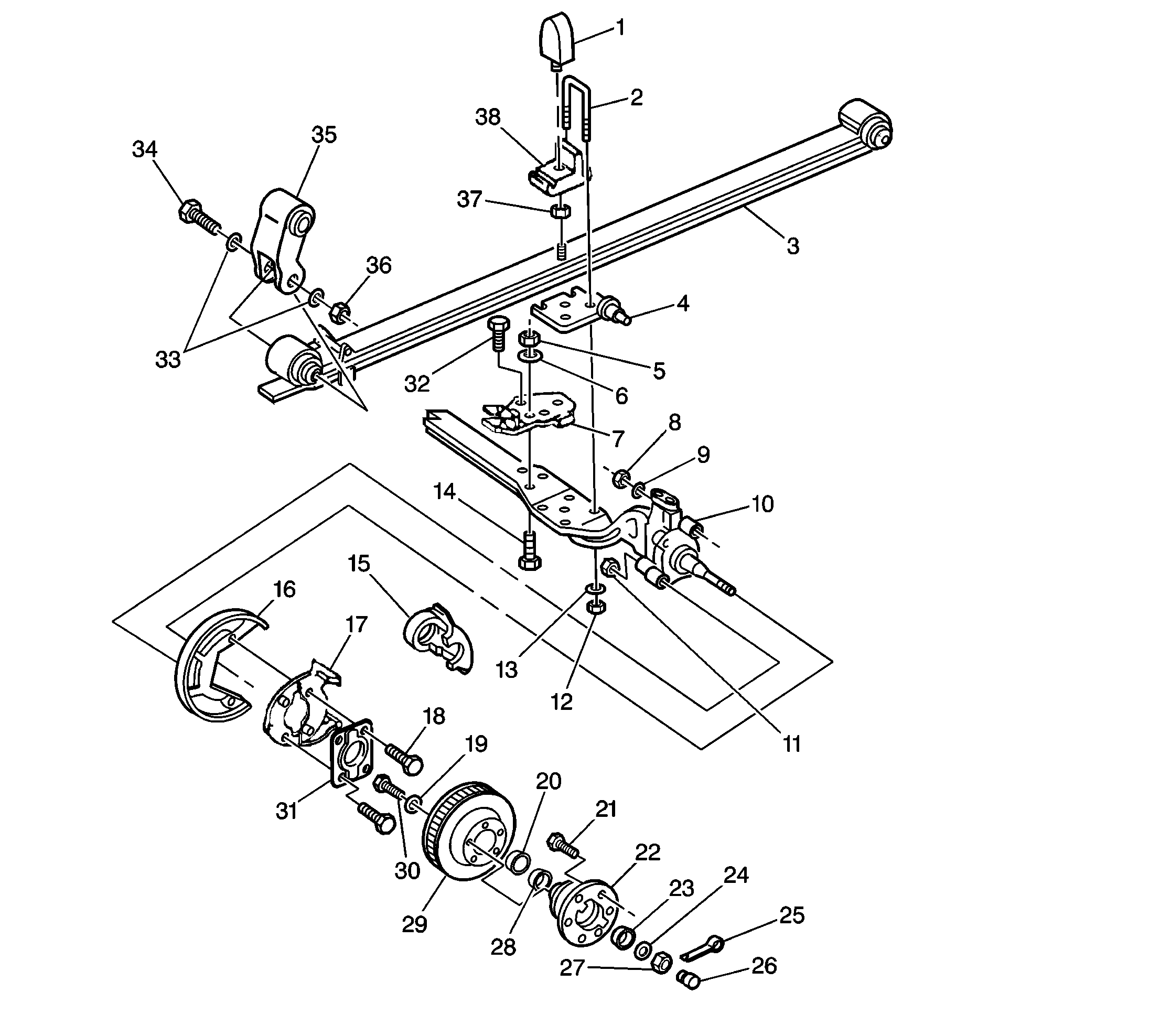
|
|---|
| (1) | Front Spring Spacer Cushion |
| (2) | Front
Spring U-bolt |
| (3) | Front Spring |
| (4) | Spring Spacer |
| (5) | Front Stabilizer Bracket Nut |
| (6) | Front Stabilizer Bracket Washer |
| (7) | Front Stabilizer Bracket |
| (8) | Steering
Knuckle Nut |
| (9) | Steering Knuckle Washer |
| (10) | Steering Knuckle |
| (11) | Steering Knuckle Nut |
| (12) | Front Spring U-bolt Nut |
| (13) | Front Spring
U-bolt Washer |
| (14) | Front Stabilizer Bracket Bolt |
| (15) | Brake Caliper |
| (16) | Splash Shield |
| (17) | Anchor Plate |
| (18) | Splash shield Bolt |
| (19) | Wheel Hub Rotor Bolt Washer |
| (20) | Bearing Seal |
| (21) | Wheel Hub Bolt |
| (22) | Wheel Hub |
| (23) | Hub Outer Bearing |
| (24) | Washer |
| (25) | Retainer Cap Cotter Pin |
| (26) | Retainer Cap |
| (27) | Wheel Bearing Nut |
| (28) | Inner Bearing |
| (29) | Hub Rotor |
| (30) | Wheel Hub Rotor
Bolt |
| (31) | Bearing Seal Shield |
| (32) | Front Stabilizer Bracket Bolt |
| (33) | Spring Hanger Washers |
| (34) | Spring Hanger to Front Spring Bolt |
| (35) | Spring
Hanger |
| (36) | Spring Hanger to Front Spring Nut |
| (37) | Cushion Nut |
| (38) | Spacer |
.

- Install the steering knuckle (10).
A new knuckle has new bushings already installed.
- Install the thrust bearing shim and the dust seal. Prelube the thrust bearing. Refer to
Fluid and Lubricant Recommendations
in Maintenance and Lubrication.
- Install the king pin (7) and the lock pin (21).
| 3.1. | Prelube the king pin. |
| 3.2. | Insert the spacers in the correct order. |
Notice: Use the correct fastener in the correct location. Replacement fasteners
must be the correct part number for that application. Fasteners requiring
replacement or fasteners requiring the use of thread locking compound or sealant
are identified in the service procedure. Do not use paints, lubricants, or
corrosion inhibitors on fasteners or fastener joint surfaces unless specified.
These coatings affect fastener torque and joint clamping force and may damage
the fastener. Use the correct tightening sequence and specifications when
installing fasteners in order to avoid damage to parts and systems.
- Install the washer (19) and the nut (18).
Tighten
Tighten the nut to 40 N·m (29 lb ft).
- Install the gaskets.
- Install the caps (15) to the steering knuckle.
- Check and if needed, adjust the king pin preload. Refer to
King Pin Bearing Preload
.
- Install the stabilizer bracket and the bolts.
Tighten
Tighten the bolts to 7 N·m (60 lb in).
- Install the steering arm, the splash shield, and the anchor plate.
- Install the bolts and the washers that attach the splash shield to the anchor plate.
- Install the bolts, the washers, and the nuts that attach the anchor plate and the steering arm to the steering knuckle.
Tighten
| • | Tighten the bolts to 16 N·m (12 lb ft). |
| • | Tighten the nuts to 312 N·m (230 lb ft). |
- Install the steering arm to the steering linkage.
- Install the hub/rotor assembly. Refer to
Front Wheel Hub, Bearing, and Seal Replacement
.
- Adjust the wheel bearings. Refer to
Wheel Bearing Adjustment
.
- Install the brake caliper. Refer to
Brake Caliper Replacement
in Disc Brakes.
- Install the tire and wheel assembly. Refer to
Tire and Wheel Removal and Installation
in Tires and Wheels.
- Lower the vehicle.
- Check the front wheel alignment. Adjust as necessary. Refer to
Wheel Alignment Measurement
in Wheel Alignment.


