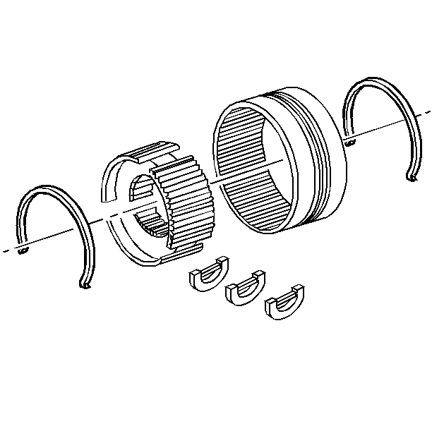
- Install the spring retainers to the synchronizer hub.
- Align the scribe marks previously made on the synchronizer hub and the synchronizer sleeve.
- Install the synchronizer hub to the synchronizer sleeve with the three struts.
- Install the main drive synchronizer stop ring to the synchronizer sleeve.
- Install the drive sprocket to the mainshaft.
- Install the synchronizer assembly to the mainshaft.
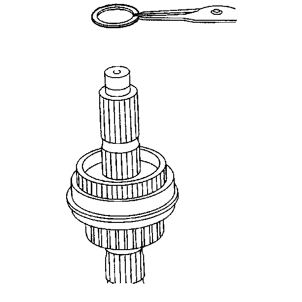
- Install the synchronizer snap ring to the mainshaft.
- Use a soft faced hammer in order to install the following components into the annulus gear:
- Install the snap ring to the input bearing.
- Apply RTV GM P/N 12345739 or equivalent to the input shaft bearing retainer mating surfaces.
- Apply threadlocker GM P/N 12345382 or equivalent to the input shaft bearing retainer bolts.
- Install the input shaft bearing retainer and the input bearing retainer bolts to the front case half.
- Install the three bolts that secure the encoder motor to the front case.
- Install the range shift hub into the front case half.
- Install the front output shaft to the front case half.
- Install the driven sprocket to the chain.
- Install the drive chain onto the drive sprocket located on the mainshaft.
- Install the driven gear snap ring to the front output shaft.
- Install the mode shift fork onto the shift rail.
- Install the mode shift fork assembly through the range shift fork, onto the synchronizer sleeve, and into the front case half.
- Install the mode fork shift spring to the shift rail.
- Install the following components into the rear case half:
- Install the oil tube O-ring into the oil pump.
- Lubricate the oil pump pickup tube with automatic transmission fluid.
- Install the dowels into the front case half.
- Wipe the case mating surfaces clean.
- Apply RTV GM P/N 12345739 or equivalent to the case mating surfaces.
- Install the rear case half over the mainshaft and onto the front case half.
- Apply threadlocker GM P/M 12345382 or equivalent to the case bolts.
- Install the case bolts into the case halves.
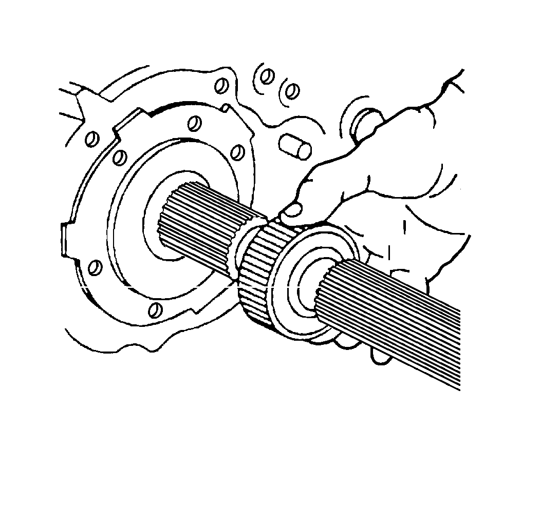
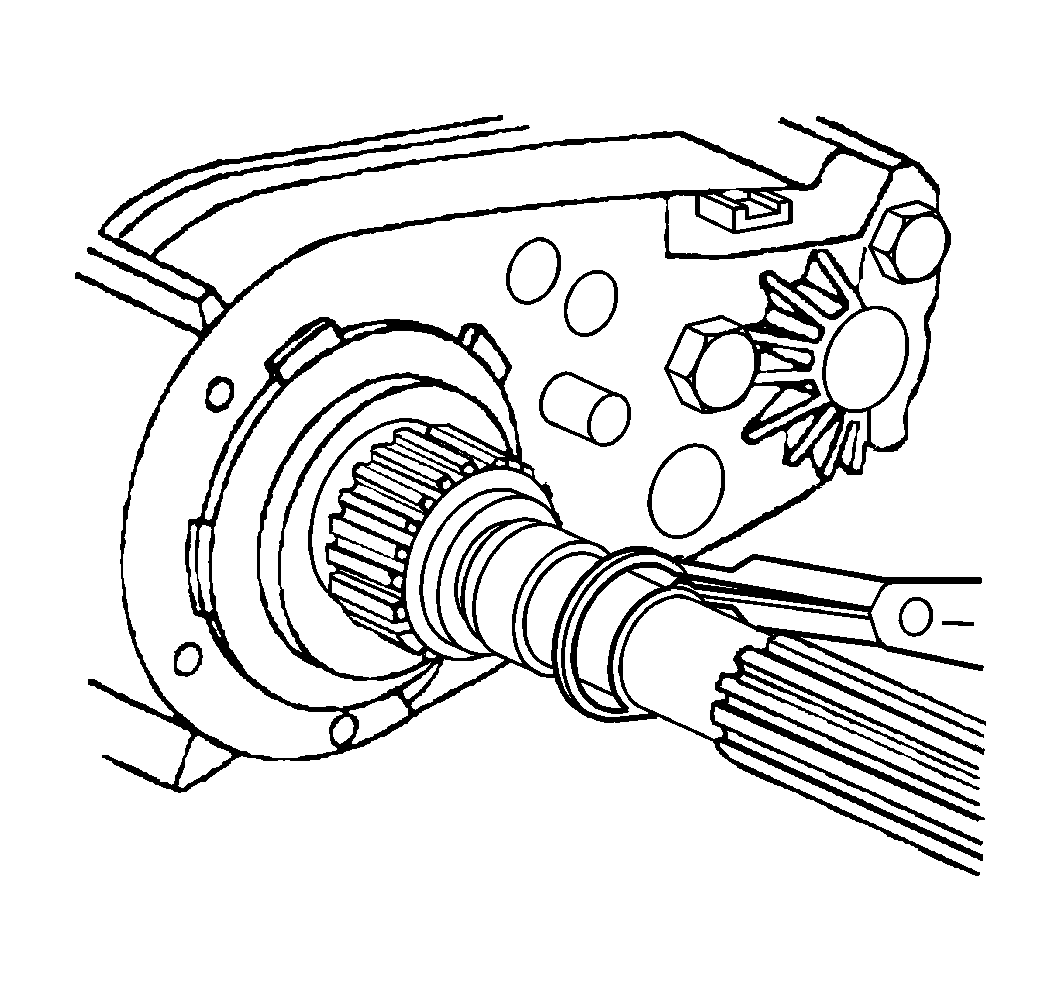
- Install the rear vehicle speed sensor rotor snap ring to the mainshaft.
- Install the vehicle speed sensor rotor onto the mainshaft.
- Install the vehicle speed sensor rotor snap ring.
- Apply threadlocker GM P/N 12345382 or equivalent to the rear retainer housing bolts.
- Install the rear retainer housing and the rear retainer housing bolts to the rear case half.
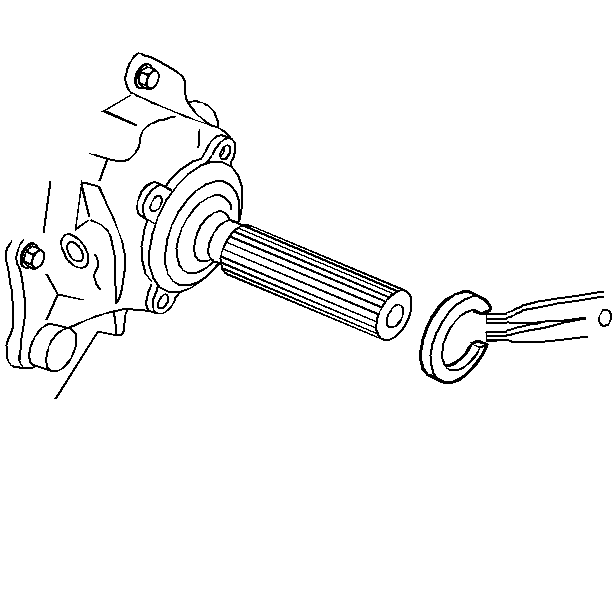
- Install the output bearing snap ring to the mainshaft.
- Apply RTV GM P/N 12345739 or equivalent to the mating surfaces.
- Apply threadlocker GM P/N 12345832 or equivalent to the extension housing bolts.
- Install the rear extension housing and the extension bolts to the rear retainer housing.
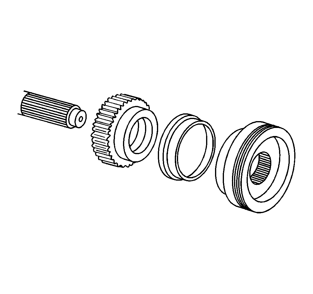
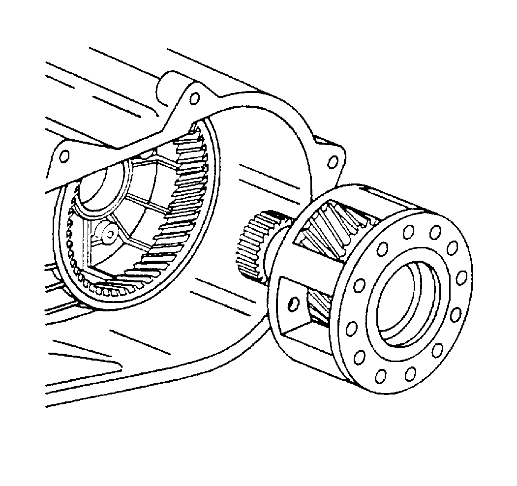
| • | The input gear |
| • | The planetary assembly |
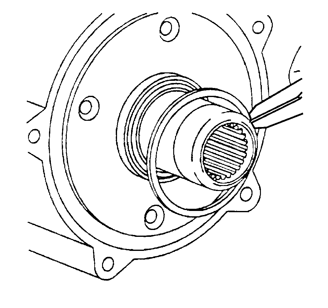
Tighten
Tighten the input bearing retainer bolts to 19 N·m (14 lb ft).
Notice: Use the correct fastener in the correct location. Replacement fasteners must be the correct part number for that application. Fasteners requiring replacement or fasteners requiring the use of thread locking compound or sealant are identified in the service procedure. Do not use paints, lubricants, or corrosion inhibitors on fasteners or fastener joint surfaces unless specified. These coatings affect fastener torque and joint clamping force and may damage the fastener. Use the correct tightening sequence and specifications when installing fasteners in order to avoid damage to parts and systems.
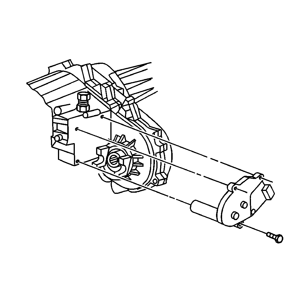
Tighten
Tighten the input bearing retainer bolts to 18 N·m (13 lb ft).
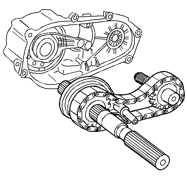
Important: The following components are installed into the front case half as an
assembly:
• The mainshaft assembly • The driven sprocket • The drive chain
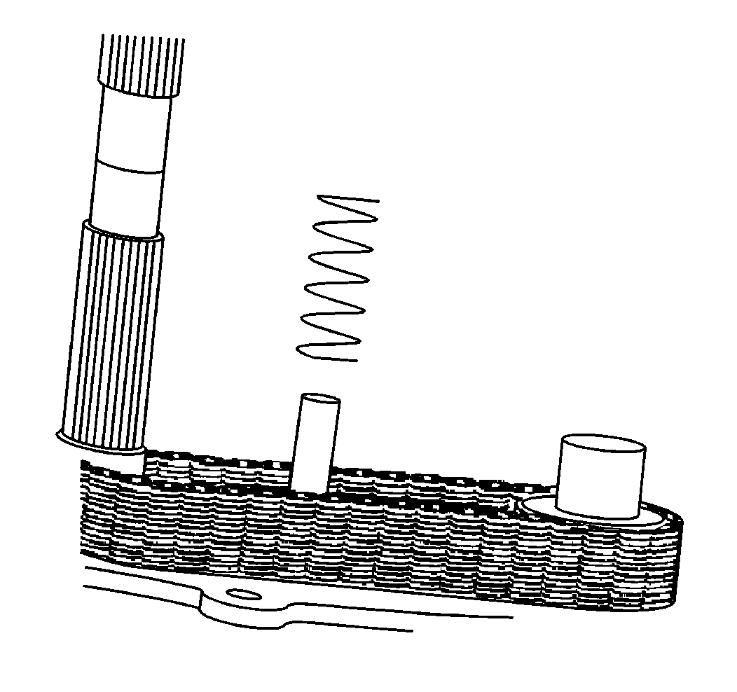
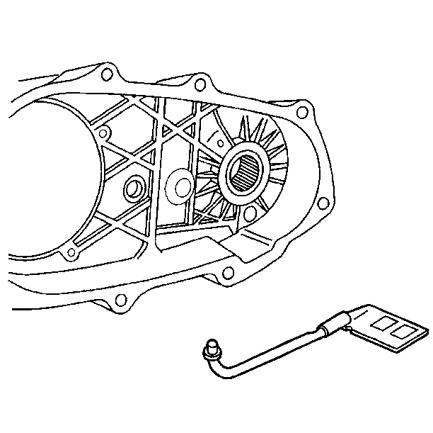
| • | The oil pump pickup tube. |
| • | The oil tube connector |
| • | The pump pickup screen |
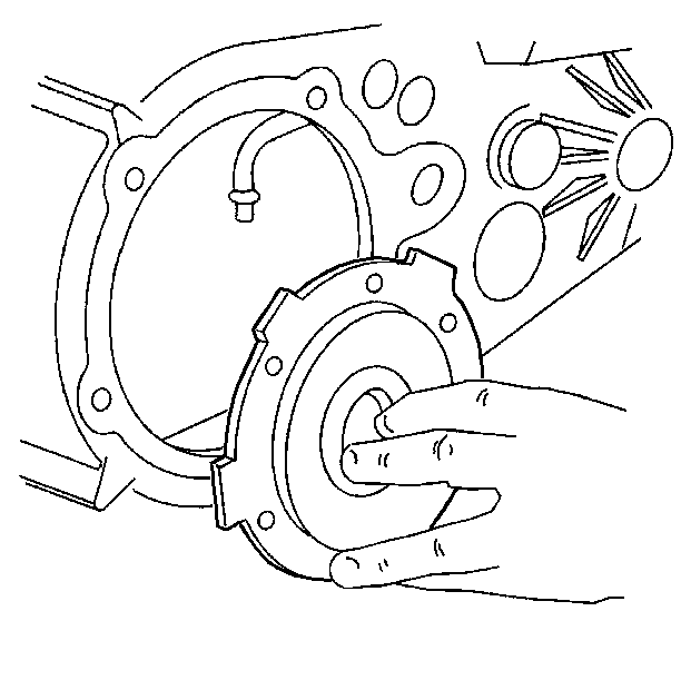
Install the oil pump to the oil pickup tube.
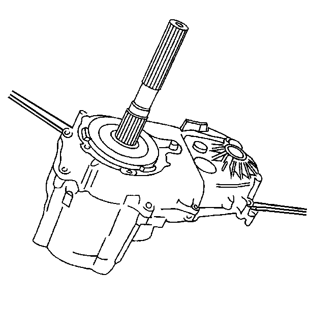
Do not damage the oil pump while installing the rear case half.
(The two longer case bolts and washers go into the doweled case holes.)
Tighten
Tighten the case bolts to 31 N·m (23 lb ft).
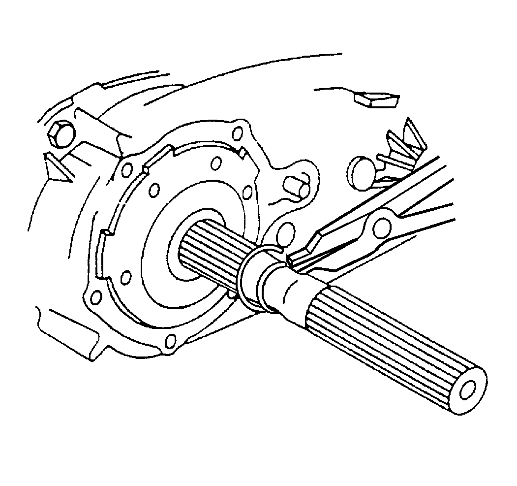
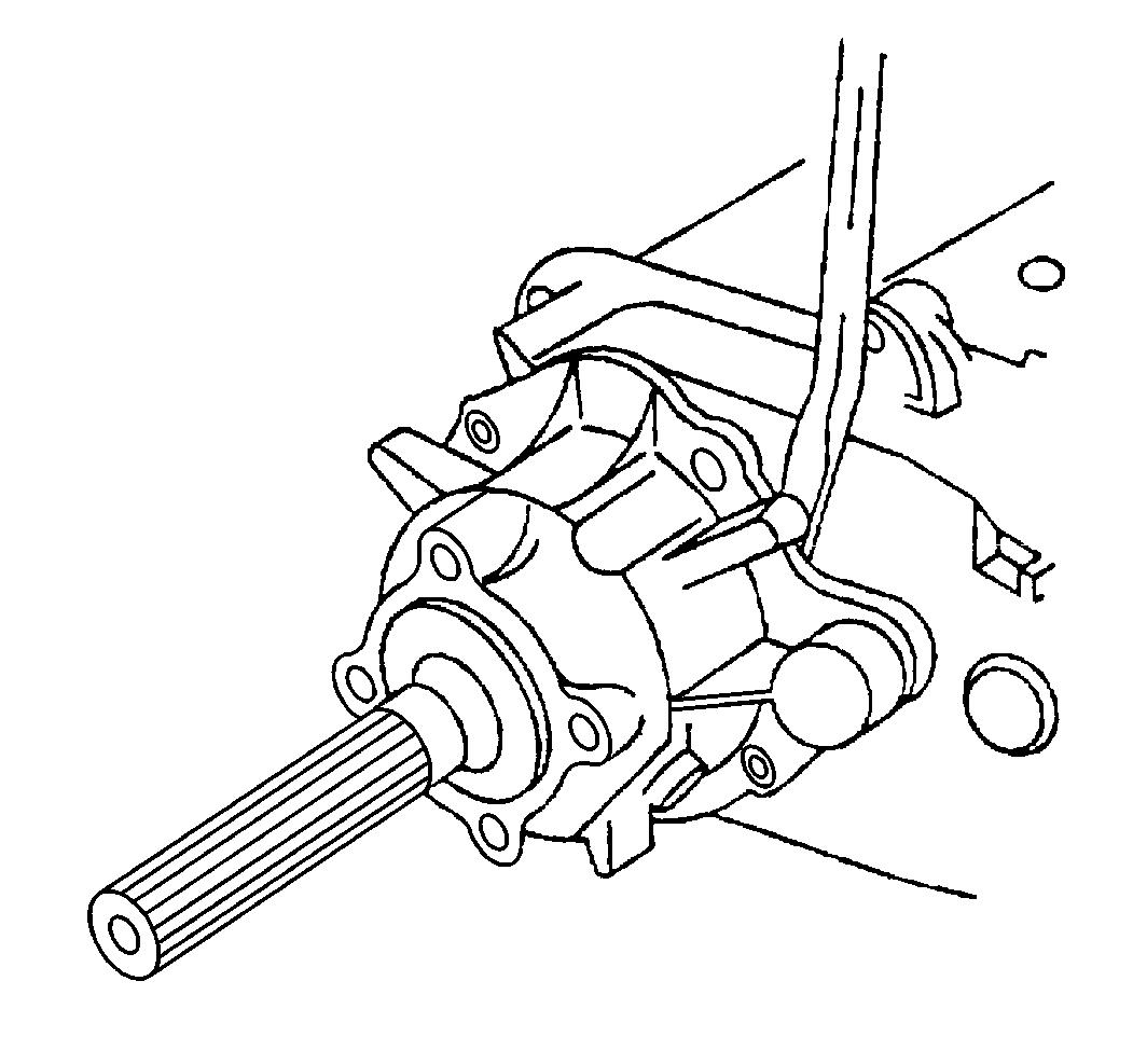
(The rear retainer housing bolts are shouldered.)
Tighten
Tighten the rear retainer housing bolts to 41 N·m (30 lb ft).
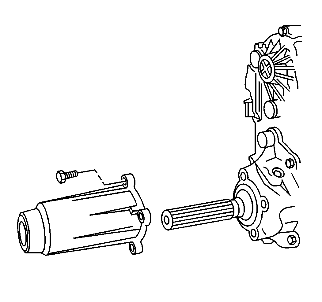
Tighten
Tighten the bolts to 31 N·m (23 lb ft).
