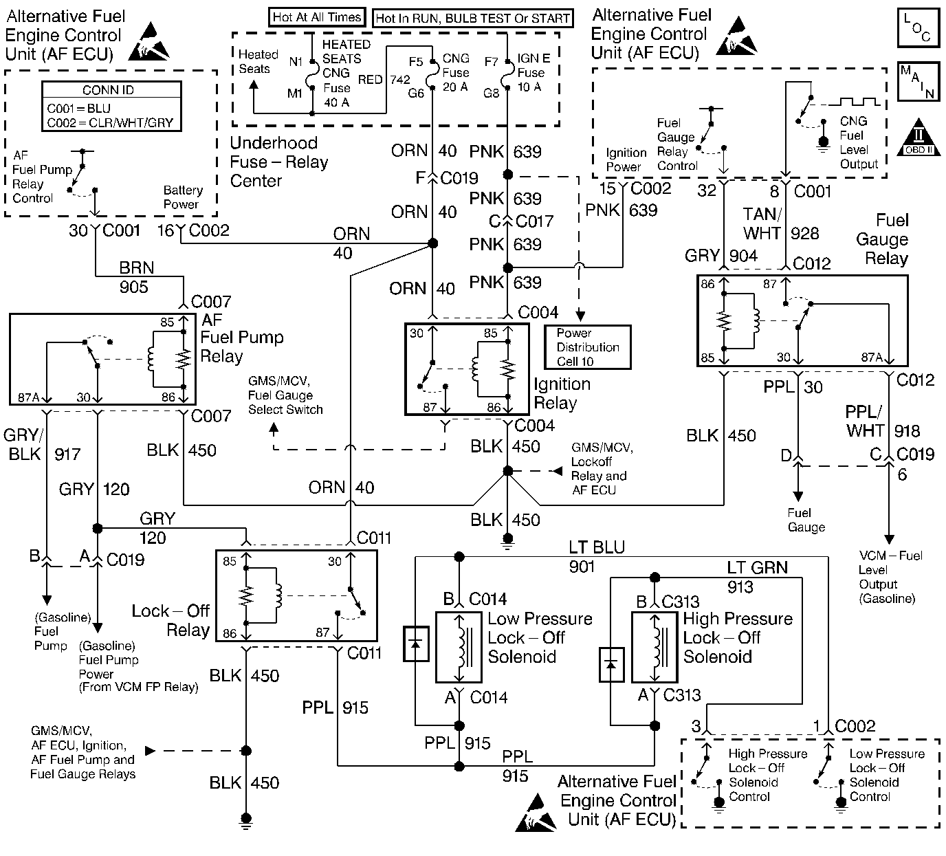
Circuit Description
The AF fuel pump relay coil is supplied a ground path all the time. The AF ECU supplies the power to the AF fuel pump relay when the engine starts and runs on CNG.
The purpose of the AF fuel pump relay circuitry is to allow the AF ECU the ability to turn OFF the gasoline fuel pump and to supply a voltage source for the lock-off relay.
At initial ignition ON the AF fuel pump relay is NOT energized by the AF ECU. The gasoline control module energizes the GASOLINE fuel pump relay supplying power to the Fuel Pump Power circuit for a 2 second prime pulse. When the prime pulse is supplied to the Fuel Pump Power circuit the lock-off relay is energized AND the gasoline fuel pump receives the 2 second prime pulse power. The 2 second prime pulse is allowed to operate the gasoline fuel pump for durabilty purposes.
When the engine is started the gasoline control module energizes the gasoline fuel pump relay supplying power to the Fuel Pump Power circuit. When the engine is operating on CNG the AF ECU energizes the AF fuel pump relay turning OFF the gasoline fuel pump. The lock-off relay continues to be energized by the gasoline fuel pump relay.
Test Description
The numbers below refer to the step numbers on the diagnostic table.
-
The AF Powertrain On-Board Diagnostic (OBD) System Check must be performed before proceeding with this diagnostic table. Failure to perform the OBD System Check will result in misdiagnosis.
-
This step checks if the engine will start and run. A failure that causes the engine to not start on either fuel can be isolated to the CNG harness or a base vehicle problem such as a malfunctioning gasoline fuel pump relay.
-
This step checks the gasoline control modules ability to supply power to the gasoline fuel pump circuit.
-
This step checks for voltage through the AF fuel pump relay. With the ignition ON and the engine OFF the AF ECU does not energize the AF fuel pump relay allowing voltage to flow through the relay and energize the gasoline fuel pump.
-
This step checks the AF ECUs ability to energize the AF fuel pump relay and disable the gasoline fuel pump during CNG operation.
-
This step checks for stuck AF fuel pump relay contacts or an open circuit between the AF fuel pump relay and the gasoline fuel pump. At ignition OFF the AF ECU turns OFF the AF fuel pump relay. At the same time, the gasoline control module energizes the gasoline fuel pump relay for several seconds.
-
If the engine did not operate on gasoline during the OBD System Check but now operates on gasoline inspect for intermittent terminal contact or a AF fuel pump relay with sticking contacts that may have been disturbed during testing.
-
This step checks if the CNG harness is the cause of the no start on gasoline.
-
If the Fuel Pump Power circuit tests OK there is a base vehicle problem that is causing the no-start condition.
Step | Action | Value(s) | Yes | No | ||||||
|---|---|---|---|---|---|---|---|---|---|---|
Did you perform the AF Powertrain On-Board Diagnostic (OBD) System Check? | -- | Go to Alternative Fuels (AF) Powertrain On Board (OBD) System Check | ||||||||
Does the engine start and run? | -- | |||||||||
Did the test lamp illuminate for approximately 2 seconds? | -- | |||||||||
4 | Does the vehicle operate on CNG but not on gasoline? | -- | Go to Alternative Fuels (AF) Powertrain On Board (OBD) System Check | |||||||
Did the test lamp illuminate for about 2 seconds? | -- | |||||||||
Does the test lamp illuminate? | -- | |||||||||
Observe the test lamp as you turn the ignition to OFF. Does the test lamp illuminate for about 2 seconds at ignition OFF? | -- | |||||||||
8 | Start and idle the engine. Backprobe the AF Fuel Pump Relay coil ground supply terminal 86 with the test lamp connected to B+. Does the test lamp illuminate? | -- | ||||||||
9 | Allow the engine to idle. Backprobe the AF Fuel Pump Relay coil power supply (control) terminal 85 with the test lamp connected to a known good ground. Does the test lamp illuminate? | -- | ||||||||
Does the engine start and run on gasoline? | -- | Go to Alternative Fuels (AF) Powertrain On Board (OBD) System Check | ||||||||
Does the engine start and run on gasoline? | -- | |||||||||
12 |
Are the repairs complete? | -- | -- | |||||||
13 |
Are the repairs complete? | -- | -- | |||||||
Was a wiring or terminal repair made? | -- | |||||||||
15 | Repair the open Fuel Pump Power circuit between the AF fuel pump relay terminal 30 and the splice. Is the repair complete? | -- | -- | |||||||
16 |
Was a terminal or wiring repair made? | -- | ||||||||
17 | Repair the open AF Fuel Pump Relay coil ground circuit between the AF Fuel Pump Relay terminal 86 and the splice. Is the repair complete? | -- | -- | |||||||
18 |
Was a terminal or wiring repair made? | -- | ||||||||
19 | Repair the open Fuel Pump circuit between the fuel pump harness connector C 019 terminal B and the AF fuel pump relay terminal 87A. Is the repair complete? | -- | -- | |||||||
20 | Replace the AF Fuel Pump relay. Is the replacement complete? | -- | -- | |||||||
21 |
Is the replacement complete? | -- | -- | |||||||
22 |
Does the vehicle operate on CNG with normal driveability, no FIL/MIL illumination, and no stored DTCs? | -- | System OK | Go to Alternative Fuels (AF) Powertrain On Board (OBD) System Check . |
