Removal Procedure
Caution: Natural gas is highly flammable. In order to reduce the risk of fire and personal injury, keep sparks, flames, and smoking materials away from the vehicle while you perform the Compressed Natural Gas (CNG) fuel system service.
- Relieve the CNG fuel system pressure. Refer to Fuel Pressure Relief .
- Disconnect the negative battery cable.
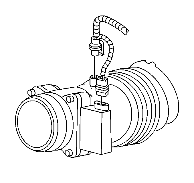
- Disconnect the mass air flow (MAF) and intake air temperature (IAT) sensor electrical connectors.
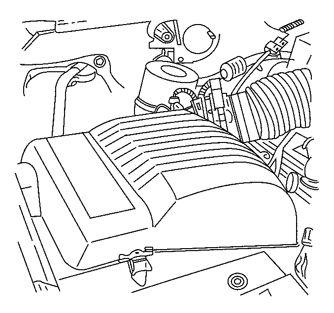
- Remove the air cleaner assembly.
- Remove the air intake duct.
- Disconnect the low pressure lock-off (LPL) electrical connector.
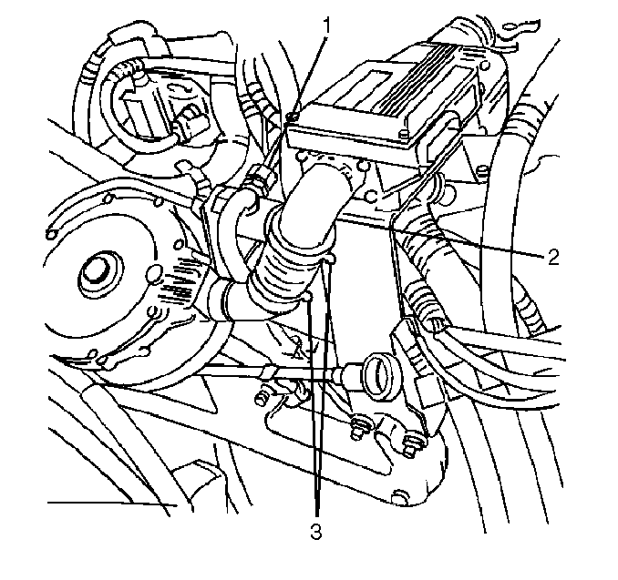
- Disconnect the fuel line from the LPL inlet fitting (1). Discard the O-ring face seal.
- Remove the 4 screws from the gas mass sensor (GMS) inlet elbow (2).
- Loosen the fuel hose clamp at the low pressure regulator (LPR) outlet elbow (3).
- Remove the fuel hose with clamps at the GMS inlet elbow.
- Remove the exhaust manifold nuts (4).
- Remove the wire harness bracket nuts.
- Remove the wire harness bracket.
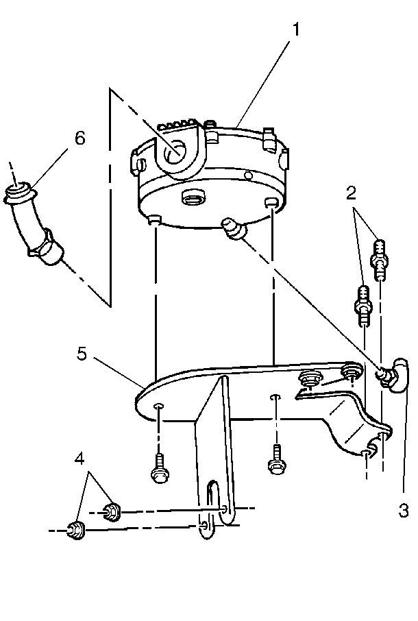
- Remove the studs (2) from the ignition coil bracket.
- Remove the LPR module.
- Remove the LPL to LPR fuel line. Discard the O-rings.
- Remove the LPR to bracket bolts.
- Remove the LPR (1) from the bracket (5).
- If replacing the LPR, disassemble the following components:
Caution: The Compressed Natural Gas (CNG) system operates at pressures up to 24820 kpa (3600 psi). Relieve the CNG fuel system pressure before servicing CNG fuel system components in order to reduce the risk of fire and personal injury.
Caution: Unless directed otherwise, the ignition and start switch must be in the OFF or LOCK position, and all electrical loads must be OFF before servicing any electrical component. Disconnect the negative battery cable to prevent an electrical spark should a tool or equipment come in contact with an exposed electrical terminal. Failure to follow these precautions may result in personal injury and/or damage to the vehicle or its components.


| • | The inlet fitting (3). |
| • | The outlet elbow (6). |
Installation Procedure
Tools Required
J 41416 Ultrasonic Leak Detector
- If replacing the LPR, assemble the following:
- Install the LPR (1) to the bracket (5).
- Install the LPR to bracket bolts.
- Install the LPL to LPR fuel line using the new O-ring face seals. Lubricate the O-ring face seals with petroleum jelly or equivalent.
- Install the LPR module.
- Install the studs (2) to the ignition coil bracket.
- Install the wire harness bracket.
- Install the wire harness bracket nuts.
- Install the exhaust manifold nuts (4).
- Install the fuel hose with clamps at the GMS inlet elbow (3).
- Install the screws to the GMS inlet elbow (2).
- Connect the fuel line to the LPL inlet (1) using a new O-ring face seal. Lubricate the O-ring face seal with petroleum jelly or equivalent.
- Connect the LPL electrical connector.
- Install the air cleaner assembly and air cleaner duct.
- Connect the MAF and IAT sensor electrical connectors.
- Connect the negative battery cable.
- Start the vehicle and use the J 41416 Ultrasonic Leak Detector in order to inspect for CNG fuel leaks at each serviced fitting.

Notice: Use the correct fastener in the correct location. Replacement fasteners must be the correct part number for that application. Fasteners requiring replacement or fasteners requiring the use of thread locking compound or sealant are identified in the service procedure. Do not use paints, lubricants, or corrosion inhibitors on fasteners or fastener joint surfaces unless specified. These coatings affect fastener torque and joint clamping force and may damage the fastener. Use the correct tightening sequence and specifications when installing fasteners in order to avoid damage to parts and systems.
Important: Apply pipe thread sealant with Teflon® to the threads of the outlet elbow and the inlet fitting before installation. Do not use Teflon® tape.
| 1.1. | Assemble the outlet elbow (6) to the LPR (1). Position the outlet elbow vertically when installing. |
Tighten
Tighten the outlet elbow finger tight plus 1 to 3 turns to the correct
position.
| 1.2. | Assemble the inlet fitting (3) to the LPR (1). Position the fitting vertically when installing. |
Tighten
Tighten the inlet fitting finger tight plus 1 to 3 turns to the correct
position.
Tighten
Tighten the bolts to 12 N·m (108 lb in).
Caution: Natural gas is stored under high pressure. If a leak occurs, the high pressure could cause a personal injury. In order to prevent Compressed Natural Gas (CNG) fuel leaks, always replace the CNG fuel system O-rings during service.
Tighten
Tighten the fittings to 37 N·m (27 lb ft).
Tighten
Tighten the studs to 12 N·m (108 lb in).
Tighten
Tighten the nuts to 9.5 N·m (84 lb in).
Tighten
Tighten the nuts to 27 N·m (20 lb ft).

Tighten
Tighten the clamps to 2 N·m (18 lb in).
Tighten
Tighten the screws to 5.4 N·m (48 lb in).
Tighten
Tighten the fitting to 37 N·m (27 lb ft).


Tighten
Tighten the negative battery terminal to 15 N·m (11 lb ft).
