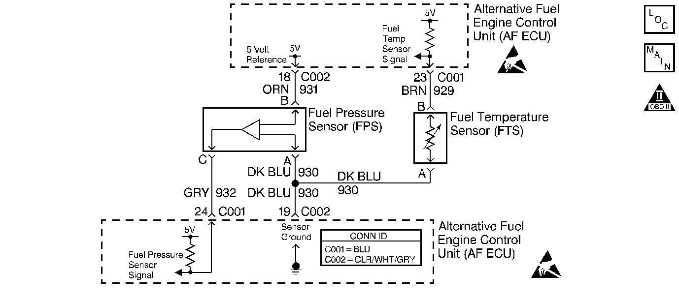
Circuit Description
The CNG fuel gauge system contains the following components:
| • | The Fuel Pressure Sensor (FPS) |
| • | The Fuel Temperature Sensor (FTS) |
| • | The Pulse Width Modulated (PWM) output circuit |
| • | The dash mounted fuel gauge |
The AF ECU monitors the fuel pressure and fuel temperature in the CNG fuel tank. Since CNG is a gas, the volume varies with pressure and temperature. In order to display an accurate fuel gauge reading, the AF ECU will perform a calculation based upon fuel pressure and temperature and determine the correct amount of fuel remaining in the fuel tank. The AF ECU converts the calculated fuel level into a PWM signal that is monitored and displayed by the instrument panel fuel gauge.
Test Description
The numbers below refer to the step numbers on the diagnostic table.
-
The other diagnostic procedures MUST be performed before proceeding with this diagnostic table. Failure to perform the diagnosis in the proper order will result in mis-diagnosis.
-
This step checks for an accurate FTS. An inaccurate FTS may cause an inaccurate CNG fuel gauge reading.
If a large difference between temperatures is observed allow the underhood and fuel tank temperatures to stabilize by not operating the vehicle for several hours with the hood raised. Repeat this step after temperatures have stabilized before proceeding with the diagnosis.
-
This step checks for an accurate FPS. An inaccurate FPS may indicate pressure when the tank is empty or an empty tank when there is sufficient pressure. Either condition would cause an unwanted switch to gasoline.
-
This step checks for the proper fuel gauge reading based upon fuel pressure and temperature.
-
This step checks if the AF ECU and the fuel gauge relay are commanding the correct fuel gauge reading.
-
This step checks for a fuel pressure sensor signal circuit that is shorted to ground.
-
This step checks the 5 volt reference circuit for proper voltage.
-
This step checks the fuel pressure sensor signal circuit and the AF ECU for proper operation.
-
This step checks for an open FPS sensor ground circuit.
-
This step checks the Fuel Temperature sensor signal circuit.
-
This step checks the fuel temperature sensor signal circuit and the AF ECU for proper operation.
Step | Action | Value(s) | Yes | No | ||||||||||
|---|---|---|---|---|---|---|---|---|---|---|---|---|---|---|
Did you perform the Fuel Gauge Selector Switch/Fuel Indicator Lamp Diagnosis and the Fuel Gauge Relay Diagnosis? | -- | Go to Fuel Gauge Selector Switch/Fuel Indicator Lamp Diagnosis | ||||||||||||
|
Important: Fast-filling the CNG fuel tank causes the fuel to heat-up and expand. The fuel temperature may remain hotter than the ambient (IAT) temperature for up to 3 hours after filling.Communicate with the AF ECU using a scan tool and observe the engine data parameters. Compare the Fuel Temperature Sensor (FTS) scan tool parameter value to the Intake Air Temperature (IAT) scan tool parameter value. Does each sensor indicate about the same temperature to within the specified value? | 20°C (35°F) | |||||||||||||
|
Important: Fast-filling the CNG fuel tank causes the fuel to heat-up and expand. The fuel tank pressure may decrease by up to 800 psi within 3 hours of filling.
Observe the scan tool data parameter while filling the CNG fuel tank. Is the FPS accurately indicating fuel tank pressure? | -- | |||||||||||||
Is the fuel gauge displaying the expected percentage of fuel? | -- | Go to Alternative Fuels (AF) Powertrain On Board (OBD) System Check | ||||||||||||
Is the measured PWM signal the same as the expected PWM signal? | -- | |||||||||||||
Is the voltage more than the specified value? | 4.9 V | |||||||||||||
Is the voltage within the specified range? | 4.7-5.2 V | |||||||||||||
If the jumper fuse opens repair the short to voltage on the signal circuit. Is the FPS voltage less than the specified value? | 0.20 V | |||||||||||||
Probe the Sensor ground circuit terminal A using the J 35616-200 Un-powered Test Lamp connected to B+. Does the test lamp illuminate? | -- | |||||||||||||
Is the voltage more than the specified value? | 4.9 V | |||||||||||||
If the jumper fuse opens repair the short to voltage on the signal circuit. Is the voltage less than the specified valu? | 0.20 V | |||||||||||||
12 | Probe the Sensor Ground circuit terminal (A) using the J 35616-200 Un-powered Test Lamp connected to B+. Does the test lamp illuminate? | -- | ||||||||||||
13 |
Was a circuit or terminal repair made? | -- | ||||||||||||
14 |
Was a circuit or terminal repair made? | -- | ||||||||||||
15 |
Was a circuit repair made? | -- | ||||||||||||
16 |
Was a circuit repair made? | -- | ||||||||||||
17 |
Was a circuit or terminal repair made? | -- | ||||||||||||
18 |
Was a circuit or terminal repair made? | -- | ||||||||||||
19 | Replace the Fuel Pressure Sensor. Refer to Fuel Pressure Sensor Replacement . Is the replacement complete? | -- | -- | |||||||||||
20 |
Important: The Fuel Temperature Sensor is NOT serviceable separately from the HPL. Replace the Fuel Temperature Sensor. Refer to High Pressure Lock-Off Solenoid Replacement . Is the replacement complete? | -- | -- | |||||||||||
21 |
Is the replacement complete? | -- | -- | |||||||||||
22 |
Does the vehicle operate on CNG with normal driveability, no FIL/MIL illumination, and no stored DTCs? | -- | System OK | Go to Alternative Fuels (AF) Powertrain On Board (OBD) System Check |
