Tools Required
| • | J 8037 Piston Ring Compressor |
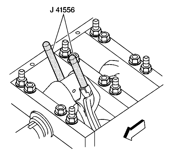
| • | J 41556 Connecting Rod Guide |
| • | J 45059 Angle Meter |
- Lightly lubricate the following components with clean engine oil:
- Position the oil control ring end gaps a minimum of 25 mm (1.0 in) from each other.
- Position the compression ring end gaps 180 degrees opposite each other.
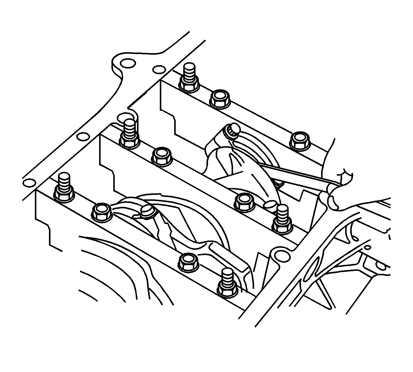
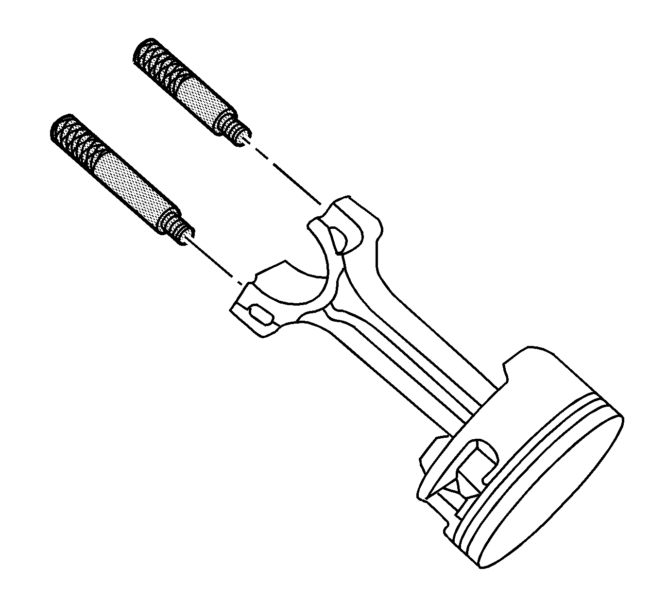
- Install the J 41556 to the connecting rod.
- Install the J 8037 onto the piston and compress the piston rings.
- Install the piston, pin, and connecting rod assembly into the cylinder bore. Hold the piston ring compressor firmly against the engine block. Using a wooden hammer handle, lightly tap the top of the piston until all the piston rings have entered the cylinder bore.
- Use the J 41556 to guide the connecting rod onto the crankshaft journal.
- Remove the J 41556 from the connecting rod.
- Identify the type of connecting rod bolt.
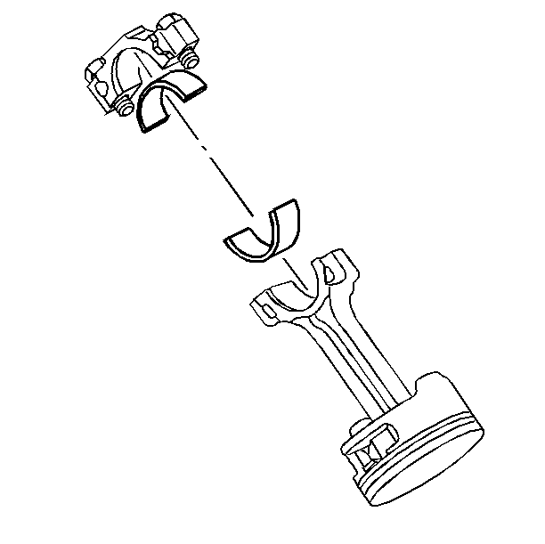
- Install the bearing cap, bearing half, and first design bolts.
- Tighten the first design bolts a first pass to 20 N·m (15 lb ft).
- Tighten the first design bolts a final pass to 85 degrees using the J 45059 .
- Install the bearing cap, bearing half, and second design bolts.
- Tighten the second design bolts a first pass to 20 N·m (15 lb ft).
- Tighten the second design bolts a final pass to 85 degrees using the J 45059 .
- Measure the connecting rods for the proper side clearance. Refer to Engine Mechanical Specifications .
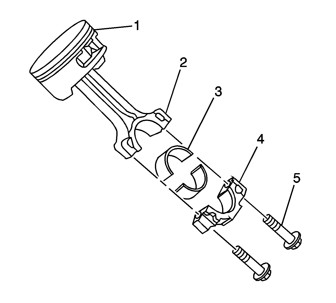
| • | Piston (1) |
| • | Piston rings |
| • | Cylinder bore |
| • | Bearings (3) and bearing surfaces |
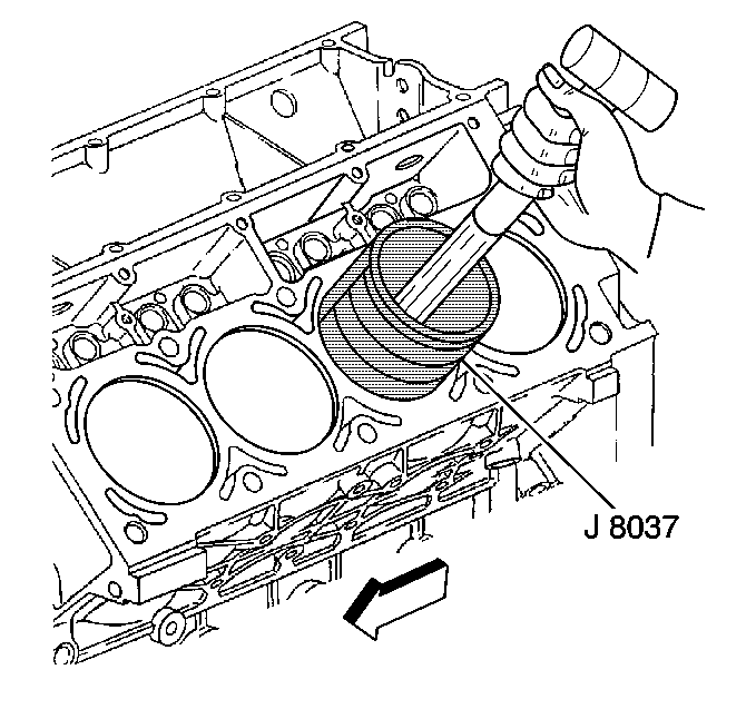
Important: The piston alignment mark MUST face the front of the engine block.
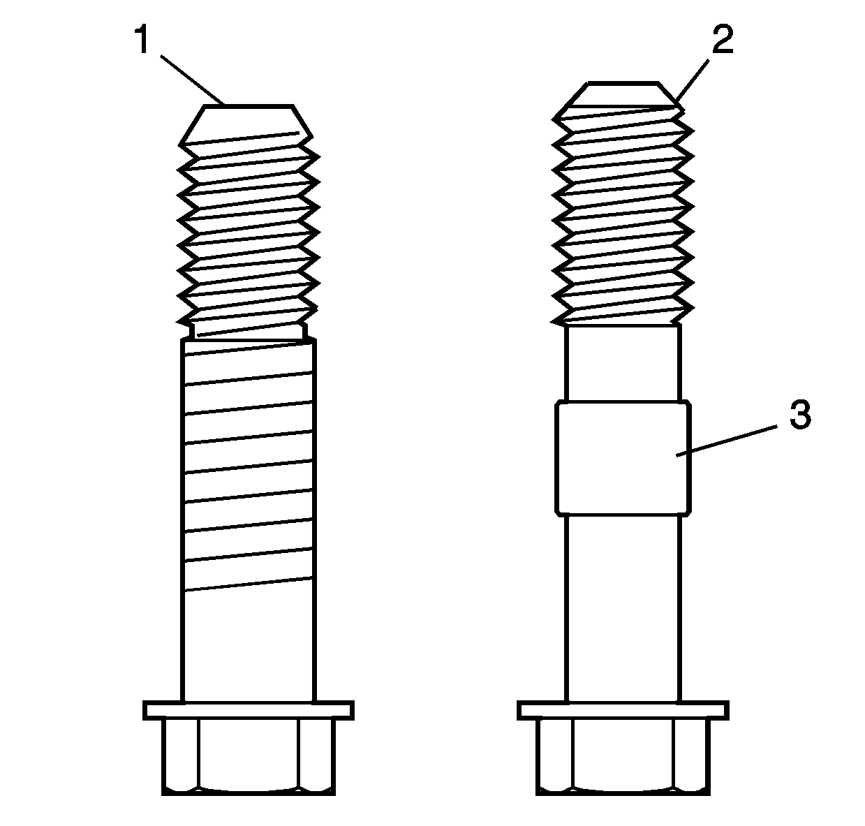
The first design connecting rod bolt (1) can be identified by a single dimple/mark on the head of the bolt and no retaining sleeve (3) on the bolt shank.
The second design connecting rod bolt (2) can be identified by two dimples/marks on the head of the bolt and a retaining sleeve (3) on the bolt shank.
Notice: Use the correct fastener in the correct location. Replacement fasteners must be the correct part number for that application. Fasteners requiring replacement or fasteners requiring the use of thread locking compound or sealant are identified in the service procedure. Do not use paints, lubricants, or corrosion inhibitors on fasteners or fastener joint surfaces unless specified. These coatings affect fastener torque and joint clamping force and may damage the fastener. Use the correct tightening sequence and specifications when installing fasteners in order to avoid damage to parts and systems.
Important: The connecting rod and cap must be assembled with the mating surfaces properly aligned.
Tighten
Tighten
