Removal Procedure
Tools Required
| • | J 34730-1A Fuel Pressure Gauge |
| • | J 37088-A Tool Set, Fuel Line Quick Connect Separator |
| • | J 43013 Fuel Injector Removal Tool |
- Disconnect the negative battery cable.
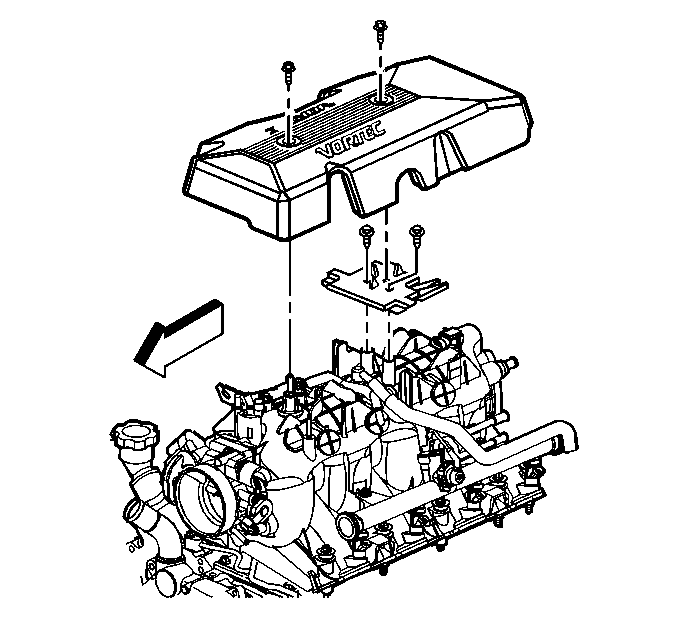
- Remove the engine sight shield.
- Relieve the fuel system pressure. Refer to the Fuel Pressure Relief Procedure .
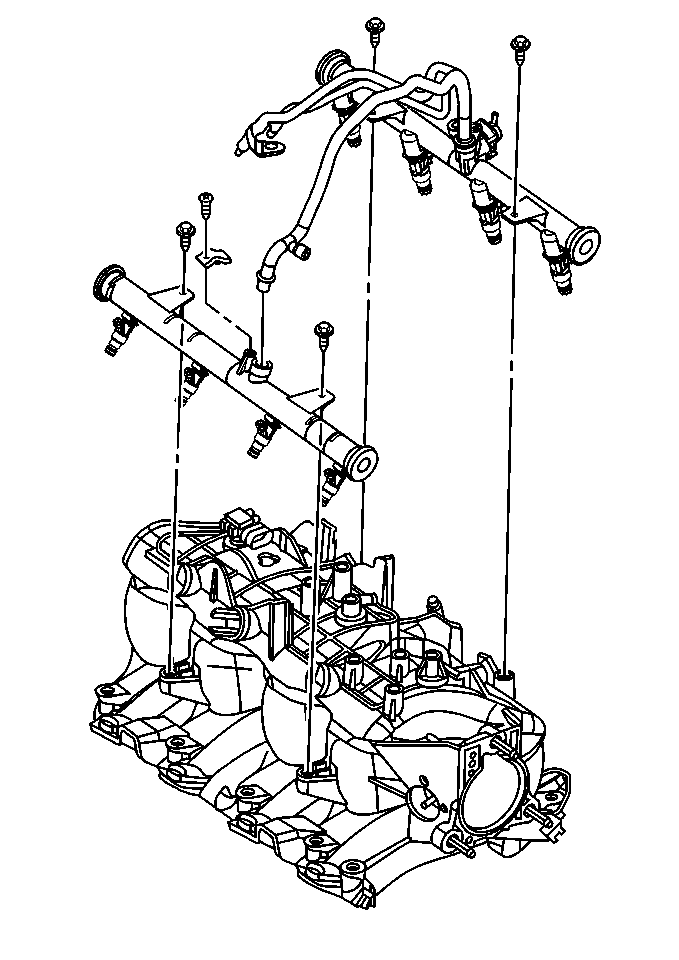
- Remove the fuel rail assembly. Refer to Fuel Injection Fuel Rail Assembly Replacement .
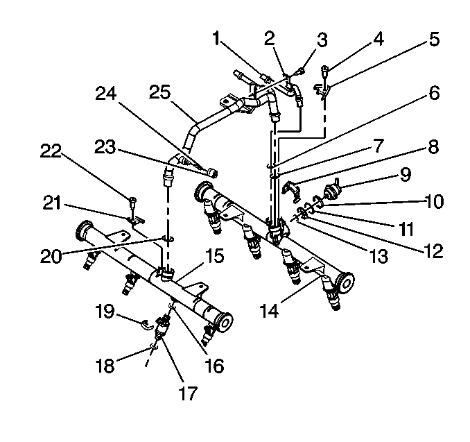
- Remove the injector retainer clip (19).
- Insert the fork of J 43013 fuel injector assembly removal tool behind the injector connector between the fuel rail pod and the 3 protruding retaining clip ledges. Use a prying motion while inserting the tool in order to force the injector out of the fuel rail pod.
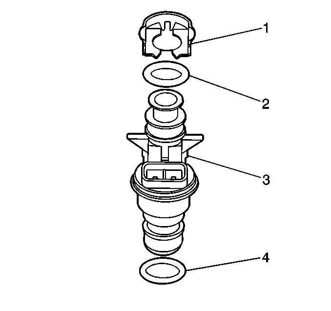
- Discard the injector retainer clip (1).
- Remove the injector O-ring seals (2 and 4) from both ends of the injector. Discard the O-ring seals.
Caution: Unless directed otherwise, the ignition and start switch must be in the OFF or LOCK position, and all electrical loads must be OFF before servicing any electrical component. Disconnect the negative battery cable to prevent an electrical spark should a tool or equipment come in contact with an exposed electrical terminal. Failure to follow these precautions may result in personal injury and/or damage to the vehicle or its components.
Important:
• Use care in removing the fuel injectors to prevent damage to the
electrical connector pins on the injector and to prevent damage to the nozzle.
Service the fuel injector as a complete assembly only. The fuel injector
is an electrical component. Do Not immerse the fuel injector in any type
of cleaner. • The engine oil may be contaminated with fuel if the fuel injectors
are leaking.
Installation Procedure
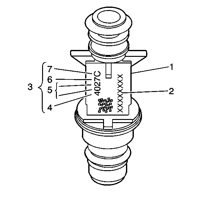
Important: When ordering new fuel injectors, be sure to order the correct injector for the application being serviced.
The fuel injector assembly (1) is stamped with a part number identification (2). A four digit build date code (3) indicates the month (4), day (5), year (6), and the shift (7) that built the injector.
- Lubricate the new injector O-ring seals (2 and 4) with clean engine oil.
- Install the new injector O-ring seals (2 and 4) on the injector.
- Install a new retainer clip (1) on the injector.
- Push the fuel injector (17) into the fuel rail injector socket with the electrical connector facing outward. The retainer clip (19) locks on to a flange on the fuel rail injector socket.
- Install the fuel rail assembly. Refer to Fuel Injection Fuel Rail Assembly Replacement .
- Tighten the fuel filler cap.
- Connect the negative battery cable.
- Inspect for leaks.
- Install the engine sight shield.


| 8.1. | Turn the ignition switch ON for 2 seconds. |
| 8.2. | Turn the ignition switch OFF for 10 seconds. |
| 8.3. | Turn the ignition switch ON. |
| 8.4. | Check for fuel leaks. |

Notice: Use the correct fastener in the correct location. Replacement fasteners must be the correct part number for that application. Fasteners requiring replacement or fasteners requiring the use of thread locking compound or sealant are identified in the service procedure. Do not use paints, lubricants, or corrosion inhibitors on fasteners or fastener joint surfaces unless specified. These coatings affect fastener torque and joint clamping force and may damage the fastener. Use the correct tightening sequence and specifications when installing fasteners in order to avoid damage to parts and systems.
Tighten
Tighten the engine sight shield bolts to 10 N·m (89 lb
in).
