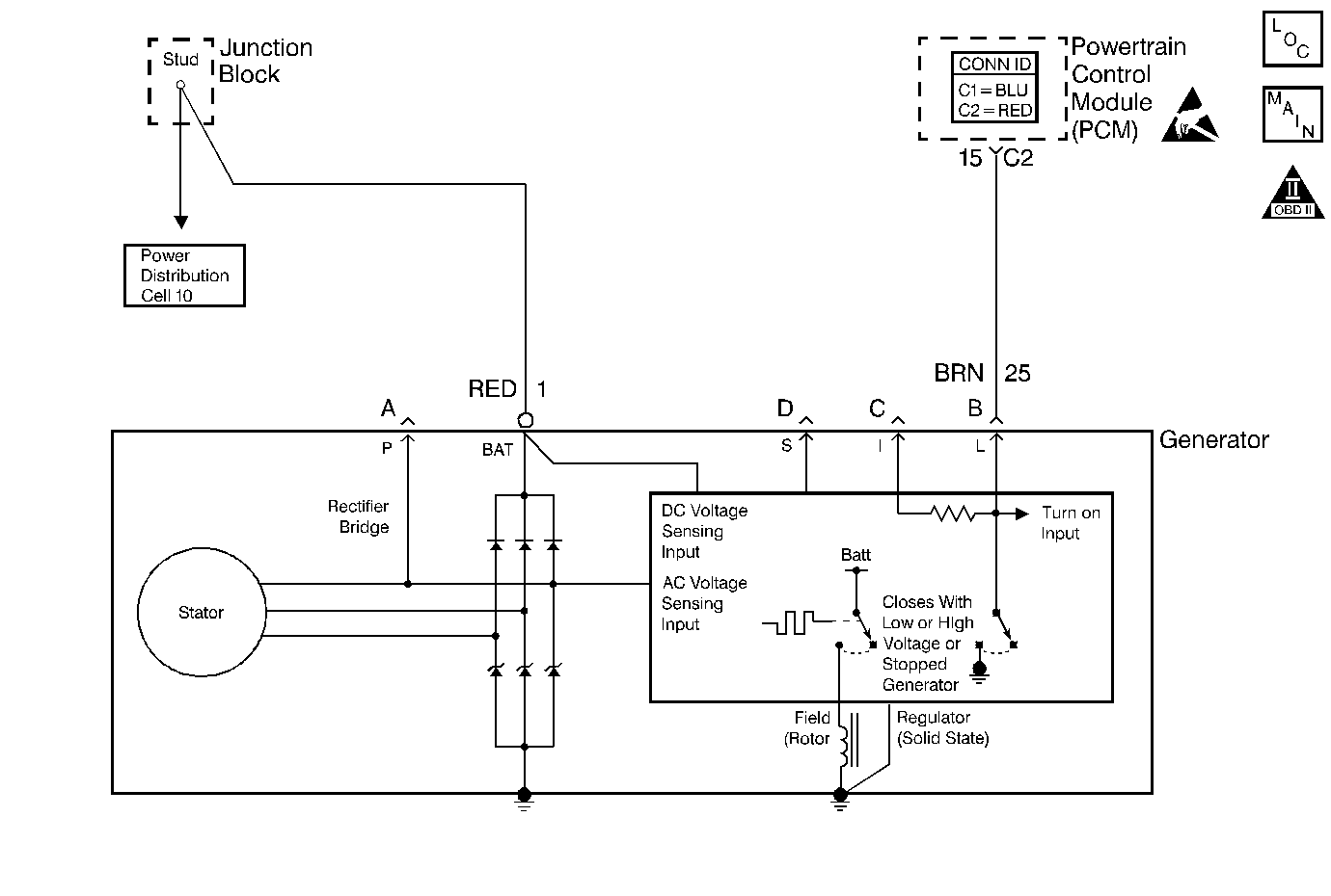
Circuit Description
The L-terminal circuit from the generator is a discrete circuit into the PCM. The PCM supplies the ignition voltage to the generator lamp feed. This ignition voltage is pulled low by the generator once the ignition switch supplies ignition 1 voltage. The voltage stays low until the generator turns. When the generator is up and running, the PCM detects ignition voltage. Therefore, with no failures with the vehicle's charging system, the lamp terminal circuit will go low (0 volts) when the ignition switch is powered up and then goes to the ignition voltage after the engine is started.
When the charging system detects a fault (circuit shorted to ground), the Instrument Panel Cluster ( IPC ) displays a message.
Diagnostic Aids
Important: Remove any debris from the PCM connector surfaces before servicing the PCM. Inspect the PCM connector gaskets when diagnosing/replacing the PCM. Ensure that the gaskets are installed correctly. The gaskets prevent water intrusion into the PCM.
| • | The following may cause an intermittent: |
| - | Poor connections: Check for adequate terminal tension. Refer to Body and Accessories/ Intermittents and Poor Connections Diagnosis for proper procedure. |
| - | Corrosion |
| - | Mis-routed harness |
| - | Rubbed through wire insulation |
| - | Broken wire inside the insulation |
| • | For an intermittent, refer to Symptoms . |
| • | A generator fault, such as a shorted output diode, malfunctioning regulator, open or shorted rotor may cause a low battery charge. Refer to Engine Electrical/ Charging System Check for further information and generator diagnosis. |
Test Description
The numbers below refer to the step numbers on the Diagnostic Table.
Step | Action | Value(s) | Yes | No |
|---|---|---|---|---|
1 | Did you perform the Powertrain On-Board Diagnostic (OBD) System Check? | -- | ||
Does the scan tool display the Generator L terminal as Inactive? | -- | |||
3 | Measure the voltage at the battery using the DMM J 39200 . Is the battery voltage within the specified range? | 13-15V | Go to Diagnostic Aids | |
4 | Probe the Generator battery feed circuit using the Test Lamp connected to ground. Refer to Measuring Voltage in Wiring Systems. Does the test lamp illuminate? | -- | Go to Charging System Check in Engine Electrical | |
5 |
Is the voltage the same or more then the value specified? | 10V | ||
6 |
Does the DMM indicate continuity? | -- | ||
7 | Repair the open/high resistance in the generator circuit. Refer to Wiring Repairs in Wiring Systems. Is the repair complete? | -- | System OK | -- |
8 |
Did you find and correct the condition? | -- | System OK | |
9 |
Important:: Program the replacement PCM. Refer to Powertrain Control Module Replacement/Programming . Replace the PCM. Is the action complete? | -- | System OK | -- |
Did you find and correct the condition? | -- | System OK | ||
11 | Repair or replace the generator. Refer to Charging System Check in Engine Electrical. Is the action complete? | -- | System OK | -- |
