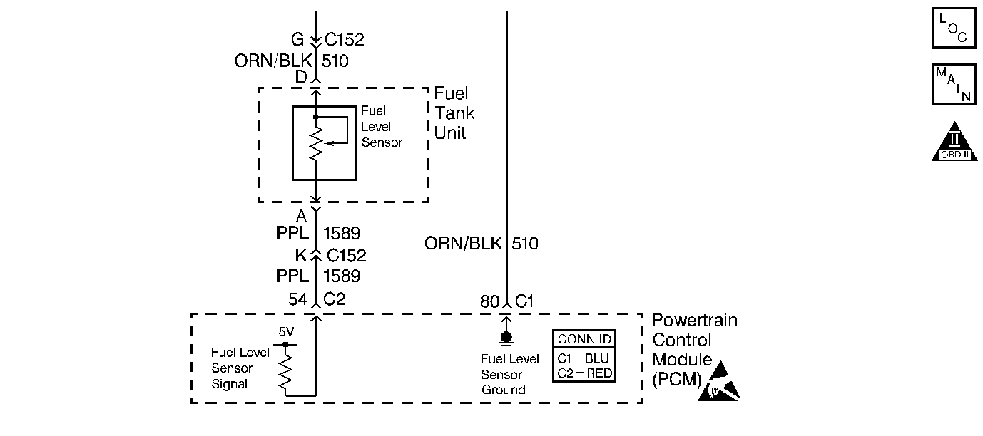
Circuit Description
The Fuel Level Sensor changes resistance based on fuel level. The Fuel Level Sensor has a signal circuit and a ground circuit. The PCM applies a voltage (about 5.0 volts) on the signal circuit to the sensor. The PCM monitors changes in this voltage caused by changes in the resistance of the sensor to determine fuel level.
When the fuel tank is full, the sensor resistance is high, therefore the PCM will sense a high signal voltage (fuel tank full). When the fuel tank is empty, the sensor resistance is low. This causes the PCM to sense a low signal voltage (fuel tank empty).
The PCM uses inputs from the Fuel Level Sensor in order to calculate the total fuel remaining in the fuel tank. The PCM uses the fuel level information for the EVAP and misfire diagnostics. The fuel level information is sent to the fuel gauge via the class 2 circuit.
Diagnostic Aids
Important: Remove any debris from the PCM connector surfaces before servicing the PCM. Inspect the PCM connector gaskets when diagnosing/replacing the PCM. Ensure that the gaskets are installed correctly. The gaskets prevent water intrusion into the PCM.
Test Description
The numbers below refer to the step numbers on the diagnostic table.
-
This step tests if the Instrument Panel Cluster (IPC) is communicating on the Class 2 circuit. The fuel gauge defaults to empty when the Class 2 circuit to the Instrument Panel Cluster (IPC) is open.
The Fuel Level information is important for diagnosis. The Fuel Level information may determine how much fuel is remaining. Inquire with the customer for Fuel Level information. Ask the customer the following questions:
-
This table is to be used only for an inaccurate fuel gauge concern. The fuel gauge defaults to empty when a Fuel Level sensor or circuit fault occurs. Also, if DTCs P1635 or P1639 are set, diagnose those DTCs first. A 5 volt reference circuit with high resistance may cause the Fuel Level to be inaccurate.
-
The gauge should be close to the scan tool commanded values (within 5%).
-
This step tests the signal circuit with high resistance when the fuel level sender is disconnected. If the signal did not reach 5 volts, it is a good indication that the signal circuit is at fault.
| • | How many miles have been traveled since the last fill-up. |
| • | When is the fuel gauge inaccurate. Depending on the current Fuel Level, it may be difficult to locate a malfunctioning sending unit. The malfunction may only occur when the fuel level is full or near empty. The fuel sending unit may need to be removed for further diagnosis. The resistance of the sensor should change smoothly from 40ohms to 250ohms. Replace the sensor if the resistance did not change smoothly or was out of range. |
Step | Action | Value(s) | Yes | No | ||||||
|---|---|---|---|---|---|---|---|---|---|---|
1 | Did you perform the Powertrain On-Board Diagnostic (OBD) System Check? | -- | ||||||||
|
Important: Before starting this diagnostic table, refer to the Test Description for this step.
Does the scan tool display the Instrument Panel Cluster (IPC) as active? | -- | Go to Diagnostic System Check - Instrument Cluster in Instrument Panel, Gauges and Console | ||||||||
Is there any Fuel Level or 5 volt reference DTCs set? | -- | Go to the applicable DTC | ||||||||
Command the fuel gauge to 100%, 50%, 25%, and 0% using the scan tool in output controls. Does the fuel gauge correspond to the commanded position of the scan tool. | -- | Go to Diagnostic System Check - Instrument Cluster in Instrument Panel, Gauges and Console | ||||||||
Does the scan tool indicate the Fuel Level voltage at the specified value? | 0 Volts | |||||||||
6 | Jumper the Fuel Level sensor ground circuit to the Fuel Level signal circuit (PCM side). Does the scan tool indicate the Fuel Level voltage at the specified value? | 0 Volts | ||||||||
7 |
Did you find and correct the condition? | -- | System OK | |||||||
8 |
Did you find and correct the condition? | -- | System OK | |||||||
9 |
Important: Before replacing the sending unit, inspect the inside of the fuel tank for objects that could be restricting the movement of the float arm. Replace the fuel Sender Assembly. Refer to Fuel Level Sensor Replacement . Is the action complete? | -- | System OK | -- | ||||||
10 |
Important: Inspect the PCM/Fuel Level sensor for poor connections and corrosion. Refer to Intermittents and Poor Connections Diagnosis in Wiring Systems. Repair the high resistance in the Fuel Level signal circuit. Refer to Wiring Repairs in Wiring Systems. Is the action complete? | -- | System OK | -- | ||||||
11 |
Important: Inspect the PCM/Fuel Level sensor for poor connections and corrosion. Refer to Intermittents and Poor Connections Diagnosis in Wiring Systems. Repair the open or the high resistance in the Fuel Level sensor ground circuit. Refer to Wiring Repairs in Wiring Systems. Is the action complete? | -- | System OK | -- |
