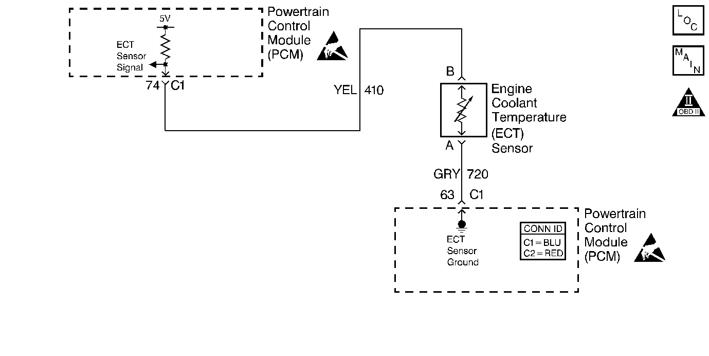
Circuit Description
The Engine Coolant Temperature (ECT) sensor contains a semiconductor device which changes the resistance based on the temperature (a thermistor). The ECT sensor is mounted in the left bank cylinder head near the front of the engine. The ECT sensor has a signal circuit and a ground circuit. The PCM applies a voltage (about 5.0 volts) on the signal circuit to the sensor. The PCM monitors the changes in this voltage caused by changes in the resistance of the sensor in order to determine the coolant temperature.
When the coolant is cold, the sensor (thermistor) resistance is high. The PCM therefore senses a high signal voltage (low temperature). When the coolant is warm, the sensor resistance is low. The PCM will sense a low signal voltage (high temperature). At normal operating temperature, the voltage should measure about 1.5-2.0 volts at the PCM.
The engine coolant temperature sensor information is sent to the Instrument Panel Cluster (IPC) via the Class 2 circuit. The IPC displays the following messages when the PCM detects higher than normal operating temperatures:
| • | When the engine coolant temperature is greater than 121°C (250°F), the IPC message center displays Check Coolant Temperature. |
| • | When the engine coolant temperature is greater than 128°C (262°F), The IPC message center displays Engine Overheated. |
Diagnostic Aids
Important: Remove any debris from the PCM connector surfaces before servicing the PCM. Inspect the PCM connector gaskets when diagnosing/replacing the PCM. Ensure that the gaskets are installed correctly. The gaskets prevent water intrusion into the PCM.
| • | The following may cause an intermittent: |
| - | Mis-routed harness |
| - | Rubbed through wire insulation |
| - | Broken wire inside the insulation |
| • | If the engine has sat overnight, the engine coolant temperature and the intake air temperature values should display within a few degrees of each other. If the temperatures are not within 3°C (5°F), refer to Temperature vs Resistance . |
For an intermittent, refer to Symptoms .
Step | Action | Value(s) | Yes | No |
|---|---|---|---|---|
1 | Did you perform the Powertrain On-Board Diagnostic (OBD) System Check? | -- | ||
2 | Are there any Instrument Panel Cluster (IPC) or Engine Coolant Temperature (ECT) sensor DTC's? | -- | Go to applicable DTCs | |
3 |
Caution: Do not remove the pressure cap from the high fill reservoir while the engine is at normal operating temperature. An unexpected release of hot engine coolant may result in severe burns. Verify that the coolant level is full. Is the coolant at the proper level? | -- | Go to Loss of Coolant in Engine Cooling. | |
4 |
Select the Diagnostic Circuit Check and then the Class 2 Message Monitor. Does the scan tool display the IPC as active? | -- | Go to Instrument Cluster System Check in Instrument Panel, Gauges and Console | |
5 |
Does the scan tool display the ECT sensor at the specified value? | -39°C (-38°F) | ||
6 | Jumper the ECT sensor connector signal circuit and ground circuit together. Does the scan tool display the ECT sensor at the specified value? | 140°C (284°F) | ||
7 |
Is the ECT resistance within range? | -- | ||
8 | Does the temperature gauge correspond to the ECT scan tool display? | -- | System OK | Go to Engine Coolant Temperature Gage Inaccurate or Inoperative in Instrument Panel, Gauges and Console. |
9 |
Inspect the PCM terminals for corrosion, low tension, poor connections. Refer to Intermittents and Poor Connections Diagnosis in Wiring Systems. Did you find and correct the condition? | -- | System OK | |
10 |
Did you find and correct the condition? | -- | System OK | |
11 | Replace the ECT sensor. Refer to Engine Coolant Temperature Sensor Replacement . Is action complete? | -- | System OK | -- |
