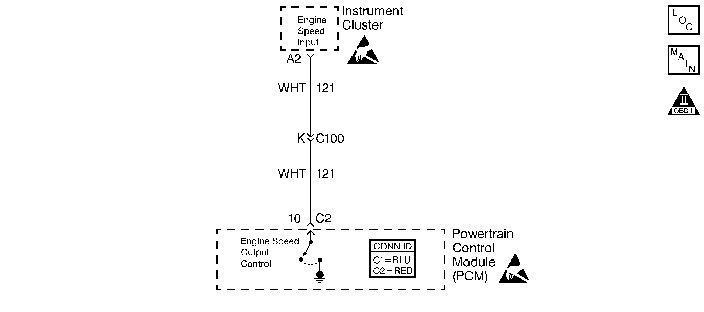
Circuit Description
The Instrument Panel Cluster (IPC) supplies a voltage to the Engine Speed Output circuit. The PCM creates the Engine Speed Output signal by rapidly grounding this circuit via an internal switch called a driver. The other components on this circuit recognize the voltage being pulled to ground as an indication of engine speed.
The driver supplies the ground for the component being controlled. Each driver has a fault line which the PCM monitors. When the PCM commands a component ON, the voltage of the control circuit should be low (near 0 volts). When the PCM commands the control circuit to a component OFF, the voltage potential of the circuit should be high (near battery voltage).
Diagnostic Aids
Important: Remove any debris from the PCM connector surfaces before servicing the PCM. Inspect the PCM connector gaskets when diagnosing/replacing the PCM. Ensure that the gaskets are installed correctly. The gaskets prevent water intrusion into the PCM.
For an intermittent, refer to Symptoms .
Test Description
The numbers below refer to the step numbers on the diagnostic table.
-
Further circuit diagnosis may require I/P removal. Test the circuit from the PCM to the tachometer for being open, shorted to ground or, voltage.
-
This step is testing for the proper signal voltage.
-
This step is testing for an open circuit between the IPC and connector C100.
-
This step is testing for a grounded circuit between the IPC and connector C100.
-
This step is testing for an open circuit between the PCM and connector C100.
Step | Action | Value(s) | Yes | No |
|---|---|---|---|---|
1 | Did you perform the Powertrain On-Board Diagnostic (OBD) System Check? | -- | ||
|
Important: If the I/P is completely inoperative, refer to Instrument Cluster System Check in Instrument Panel, Gauges and Console.
Does the vehicle's tachometer indicate an engine RPM? | -- | Go to Diagnostic Aids | ||
Does the DMM display a voltage greater than the specified value? | 9.5V | |||
Does the DMM display continuity? | -- | |||
Test continuity from the engine output speed circuit to battery ground. Refer to Testing for Continuity in Wiring Systems. Does the DMM display continuity? | -- | |||
6 |
Refer to Intermittents and Poor Connections Diagnosis in Wiring Systems. Did you find and repair the condition? | -- | System OK | Go to Diagnostic System Check - Instrument Cluster in Instrument Panel, Gauges and Console |
Does the DMM display continuity. | -- | |||
8 | Test the continuity of the engine speed output circuit from the PCM harness connector to ground using a DMM J 39200 . Refer to Testing for Continuity in Wiring Systems. Does the DMM display continuity? | -- | ||
9 | Repair the open engine speed output circuit from the IPC to connector C100. Refer to Wiring Repairs in Wiring Systems. Is the action complete? | -- | System OK | -- |
10 | Repair the grounded engine speed output circuit from the IPC to connector C100. Refer to Wiring Repairs in Wiring Systems. Is the action complete? | -- | System OK | -- |
11 | Repair the open engine speed output circuit from the PCM to C100. Refer to Wiring Repairs in Wiring Systems. Is the action complete? | -- | System OK | -- |
12 | Repair the grounded engine speed output circuit from the PCM to C100. Refer to Wiring Repairs in Wiring Systems. Is the action complete? | -- | System OK | -- |
13 |
Refer to Repairing Connector Terminals in Wiring Systems. Did you find and repair the condition? | -- | System OK | |
14 |
Important:: Program the replacement PCM. Refer to Powertrain Control Module Replacement/Programming . Replace the PCM. Is the replacement complete? | -- | System OK | -- |
