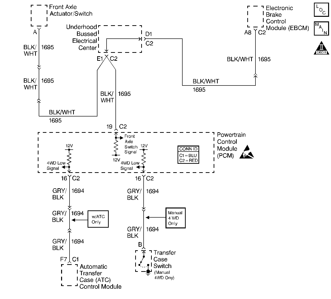
Circuit Description
When the four wheel drive selector is placed into a four wheel drive position, the transfer case switch closes and applies a ground to the front axle actuator/switch. The front axle actuator/switch is then engaged and a voltage is supplied to the PCM (front axle switch input) to indicate the vehicle is four wheel drive. The PCM then modifies transmission shift patterns based on this input. The PCM also sends a class 2 message to the IPC to illuminate the 4WD indicator.
Diagnostic Aids
Important: Remove any debris from the PCM connector surfaces before servicing the PCM. Inspect the PCM connector gaskets when diagnosing/replacing the PCM. Ensure that the gaskets are installed correctly. The gaskets prevent water intrusion into the PCM.
| • | The following may cause an intermittent: |
| - | Mis-routed harness |
| - | Rubbed through wire insulation |
| - | Broken wire inside the insulation |
| • | For an intermittent, refer to Symptoms . |
Step | Action | Value(s) | Yes | No |
|---|---|---|---|---|
1 | Did you perform the Powertrain On-Board Diagnostic (OBD) System Check? | -- | ||
2 | Is the customers concern that four wheel drive does not engage? | -- | Go to Front Axle Will Not Engage in Transfer Case | |
3 | Is the customers concern that the four wheel drive indicator is ON at all times or OFF at all times? | -- | ||
4 |
Does the 4WD indicator go ON and OFF when commanded? | -- | Go to Instrument Cluster System Check Instrument Panel, Gauges and Console | |
5 | Inspect the 4WD fuse in the left I/P electrical center. Is the fuse open? | -- | ||
6 |
Does the test lamp illuminate? | -- | ||
7 |
Does the 4WD parameter display Engaged when the Front Axle Actuator\Switch is connected to B+? | -- | ||
8 |
Is continuity indicated on the DMM? | -- | ||
9 | Check continuity of the Front Axle Actuator\Switch signal circuit to ground using the DMM J 39200 . Refer to Testing for Continuity in Wiring Systems. Is continuity indicated on the DMM? | -- | ||
10 |
Does the scan tool display 4WD low changing from Engaged to Disengaged with movement of the transfer case selector? | -- | Go to Diagnostic Aids | |
11 |
Does the scan tool display 4WD Low as Engaged? | -- | ||
12 |
Does the DMM display a resistance within the specified range? | 0-5ohms | ||
13 | Check continuity from the transfer case switch input circuit to ground using a DMM J 39200 . Refer to Testing for Continuity in Wiring Systems. Does the DMM display a resistance within the specified range? | 0-5ohms | ||
14 | Repair the short to ground between the left I/P electrical center and the Front Axle Actuator\Switch. Refer to Body and Accessories/ Wiring Repairs in Wiring Systems. Is the action complete? | -- | System OK | -- |
15 | Repair the Front Axle Actuator\Switch B+ supply circuit for an open between the left I/P electrical center and the Front Axle Actuator\Switch. Refer to Wiring Repairs in Wiring Systems. Is the action complete? | -- | System OK | -- |
16 | Replace the Front Axle Actuator\Switch. Refer to Electric Motor Actuator Replacement in Front Drive Axle. Is the action complete? | -- | System OK | -- |
17 | Repair the open Front Axle Actuator\Switch signal circuit between the PCM and the Front Axle Actuator\Switch. Refer to Wiring Repairs in Wiring Systems. Is the action complete? | -- | System OK | -- |
18 | Repair the grounded Front Axle Actuator\Switch signal circuit between the PCM and the Front Axle Actuator\Switch. Refer to Wiring Repairs in Wiring Systems. Is the action complete? | -- | System OK | -- |
19 | Replace the Transfer Case switch. Refer to Transfer Case Control Component Views in Transfer Case - NVG 261 - NP2. Is the action complete? | -- | System OK | -- |
20 | Repair the open transfer case switch input signal circuit between the PCM and the transfer case switch. Refer to Wiring Repairs in Wiring Systems. Is the action complete? | -- | System OK | -- |
21 | Repair the grounded transfer case switch input signal circuit between the PCM and the transfer case switch. Refer to Wiring Repairs in Wiring Systems. Is the action complete? | -- | System OK | -- |
22 |
Did you find and repair the condition? | -- | System OK | |
23 |
Important:: Program the replacement PCM. Refer to Powertrain Control Module Replacement/Programming . Replace the PCM. Is the replacement complete? | -- | System OK | -- |
