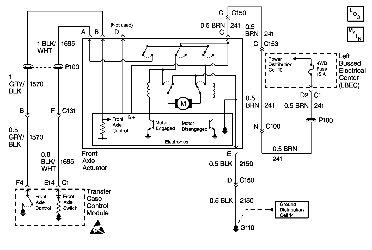
Circuit Description
The front axle control circuit consists of an electric motor actuator which engages and disengages the front axle. The front axle actuator's motor consists of a Permanent Magnetic (PM) motor, a worm gear controlled plunger, a front axle switch and an electronic control circuit all within the actuator assembly.
The front axle actuator has four circuits connected to it. Circuit 241 supplies ignition voltage to the actuator. Circuit 2150 provides the ground. Circuit 1695 is the front axle switch, and circuit 1570 is the front axle control.
Whenever a shift to AUTO, 4WD, 4HI, or 4LO is requested, the automatic transfer case control module engages the front axle by grounding the front axle control circuit 1570 through a current limiting driver.
Test Description
The number(s) below refer to the step number(s) on the diagnostic table.
-
This step determines if the front axle actuator has a good power and ground supplied to it.
-
This step determines if the transfer case shift control module is providing the ground signal to the front axle actuator through terminal B in order to drive the front axle actuator motor.
-
This step determines if the transfer case shift control module is able to sense voltage on CKT 1695.
Step | Action | Value(s) | Yes | No |
|---|---|---|---|---|
1 | Was the Transfer Case Diagnostic System Check performed? | -- | Go to Step 2 | |
2 |
Does the Front Axle Switch display change from Unlocked to Locked? | -- | Go to Step 6 | Go to Step 3 |
Is the voltage within the value specified? | 9-14 V | Go to Step 4 | Go to Step 9 | |
Is the voltage reading within the specified values? | 9-14 V | Go to Step 5 | Go to Step 14 | |
Does the Scan Tool show the Front Axle Switch status Locked? | -- | Go to Step 17 | Go to Step 7 | |
6 | Inspect the front axle for mechanical concerns, if no mechanical concerns are present replace the Front Axle Actuator. Refer to Electric Motor Actuator Replacement . Is the repair complete? | -- | Go to Step 19 | -- |
7 |
Is the resistance reading within the specified values? | 0-3 ohms | Go to Step 16 | Go to Step 8 |
8 | Repair open in CKT 1695. Refer to Wiring Repairs in Wiring Systems. Is the repair complete? | -- | Go to Step 19 | -- |
9 |
Is the voltage reading within the specified values? | 9-14 V | Go to Step 10 | Go to Step 11 |
10 | Repair open in CKT 2150. Refer to Wiring Repairs in Wiring Systems. Is the repair complete? | -- | Go to Step 19 | -- |
11 | Inspect the 4WD fuse in CKT 241 for continuity. Is the fuse good? | -- | Go to Step 12 | Go to Step 13 |
12 | Repair open in CKT 241. Refer to Wiring Repairs in Wiring Systems. Is the repair complete? | -- | Go to Step 19 | -- |
13 |
Is the fuse good? | -- | Go to Step 19 | Go to Step 18 |
14 |
Is the resistance reading within the specified values? | 0-2 ohms | Go to Step 16 | Go to Step 15 |
15 | Repair open in CKT 1570. Refer to Wiring Repairs in Wiring Systems. Is the repair complete? | -- | Go to Step 19 | -- |
16 | Replace the transfer case shift control module. Refer to Transfer Case Shift Control Module Replacement . Is the action complete? | -- | Go to Step 19 | -- |
17 | Replace the front axle actuator. Refer to Electric Motor Actuator Replacement . Is the action complete? | -- | Go to Step 19 | -- |
18 | Repair short to ground in CKT 241. Refer to Wiring Repairs in Wiring Systems. Is the repair complete? | -- | Go to Step 19 | -- |
19 |
Have all the ATC components been reconnected and properly mounted? | -- | Go to Step 20 | -- |
20 | Clear all ATC DTCs. Have all the ATC DTCs been cleared? | -- | -- |
