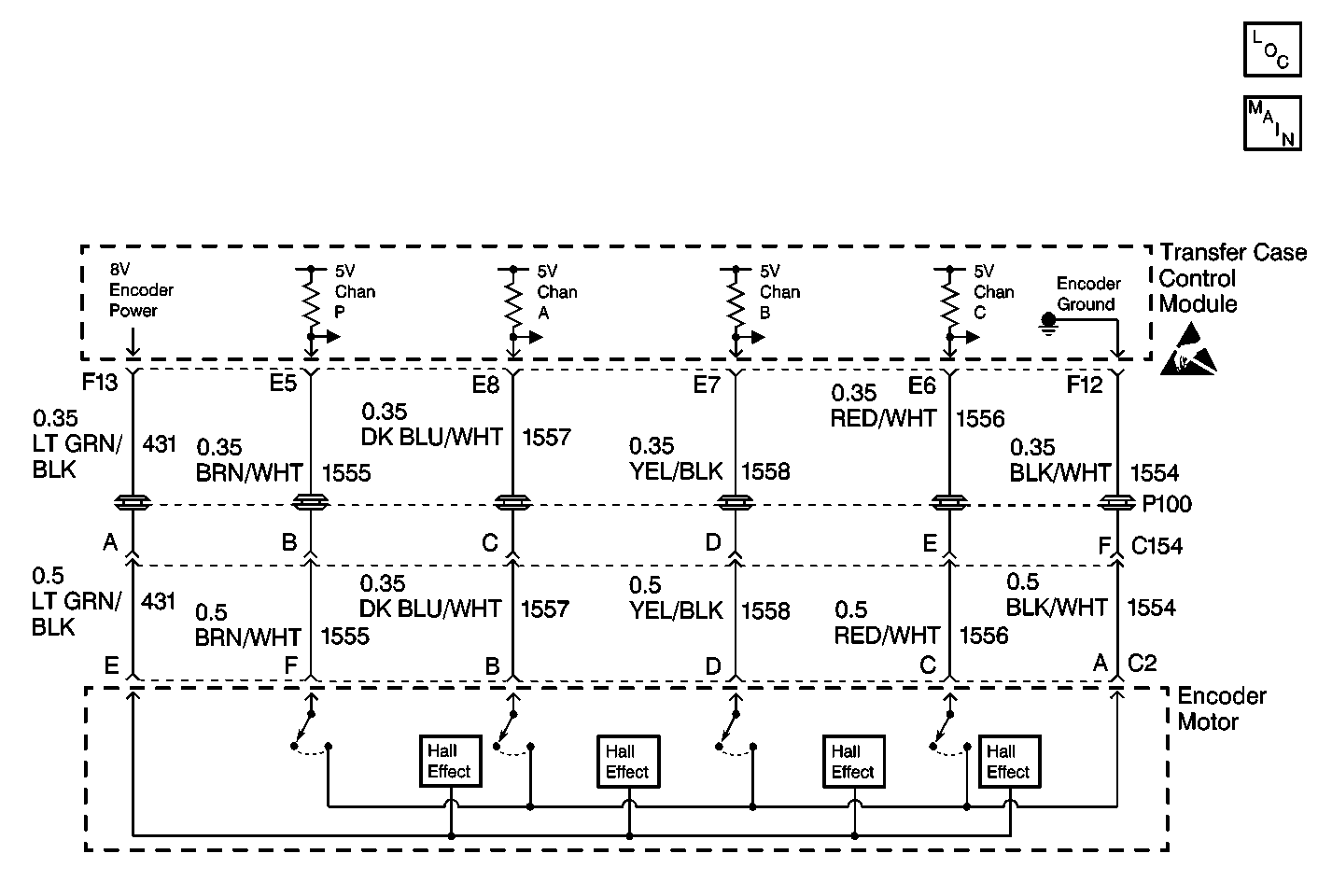
Circuit Description
The transfer case encoder motor is a bi-directional, permanent magnet, DC motor. The motor, through a series of gears, rotates a sector shaft which moves the mode and range forks to shift the transfer case between 4H, AUTO (Adapt), 2H, N, and 4L ranges. The transfer case encoder motor is used to perform the requested shift, the motor lock holds the clutch pack in place, and the encoder is used to provide feedback.
This DTC detects that the transfer case is unable to successfully complete a shift to a requested mode or range.
Conditions for Setting the DTC
| • | The transfer case shift control module will test the motor circuits and determine that there are no motor faults existing. |
| • | The transfer case shift control module has attempted to shift to a requested mode/range and has failed to reach the desired position. |
| • | The transfer case shift control module has performed a default shift to 4LO or 4HI. |
Action Taken When the DTC Sets
| • | The SERVICE indicator (AWD/4WD) lamp will be latched on for the remainder of the current ignition cycle. |
| • | All shifting will be disabled. |
| • | The range/mode lights will be disabled |
| • | The next ignition cycle, the tranfer case shift control module will power-up as if the 4HI was the mode present when the ATC was powered down. |
Conditions for Clearing the DTC
| • | The transfer case shift control module will clear the DTC if the condition for setting the DTC no longer exists. |
| • | A history DTC will clear after 100 consecutive ignition cycles without a fault present. |
| • | History DTCs can be cleared using a scan tool. |
Test Description
The number(s) below refer to the step number(s) on the diagnostic table.
-
This step check to see if the encoder motor moves.
-
This step determines if the transfer case sector shaft is bound up.
-
This step tests the continuity of the effected encoder circuits.
-
This step tests the effected encoder circuits for a short to ground.
-
This step tests the effected encoder circuits for a short to voltage.
-
This step determines if the transfer case sector shaft is bound up.
Step | Action | Value(s) | Yes | No |
|---|---|---|---|---|
1 | Was the Transfer Case Diagnostic System Check performed? | -- | Go to Step 2 | |
Do all the Encoder Circuits change between ON and OFF? | -- | Go to Step 3 | Go to Step 4 | |
Does the transfer case sector shaft bind? | -- | Go to Step 9 | Go to Step 10 | |
4 | Do any of the Encoder Circuits change states? | -- | Go to Step 5 | Go to Step 8 |
Is the resistance reading within the specified values? | 0-2 ohms | Go to Step 6 | Go to Step 11 | |
Connect a J 39200 DMM between the effected circuit(s) and ground. Is the resistance reading within the specified value? | OL | Go to Step 7 | Go to Step 12 | |
Is the voltage reading within the specified value? | 0 V | Go to Step 14 | Go to Step 13 | |
Does the transfer case sector shaft bind? | -- | Go to Step 9 | Go to Step 14 | |
9 | Remove the transfer case for repair. Refer to Transfer Case Replacement . Are the repairs complete? | -- | Go to Step 15 | -- |
10 | Replace the transfer case shift control module. Refer to Transfer Case Shift Control Module Replacement . Is the action complete? | -- | Go to Step 15 | -- |
11 | Repair open in the suspect circuit. Refer to Wiring Repairs in Wiring Systems. Are the repairs complete? | -- | Go to Step 15 | -- |
12 | Repair a short to ground condition in the effected circuit. Refer to Wiring Repairs in Wiring Systems. Are the repairs complete? | -- | Go to Step 15 | -- |
13 | Repair a short to voltage condition in the effected circuit. Refer to Wiring Repairs in Wiring Systems. Are the repairs complete? | -- | Go to Step 15 | -- |
14 | Replace the transfer case encoder motor. Refer to Motor/Encoder Replacement . Is the action complete? | -- | Go to Step 15 | -- |
15 |
Have all the ATC components been reconnected and properly mounted? | -- | Go to Step 16 | -- |
16 | Clear all ATC DTCs. Have all ATC DTCs been cleared? | -- | -- |
