Locking Differential Cam Unit Disassemble 8.6 Inch Axle
- Remove the guide clips.

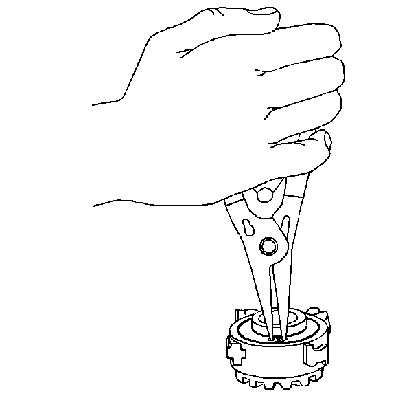
- Remove the retaining ring.

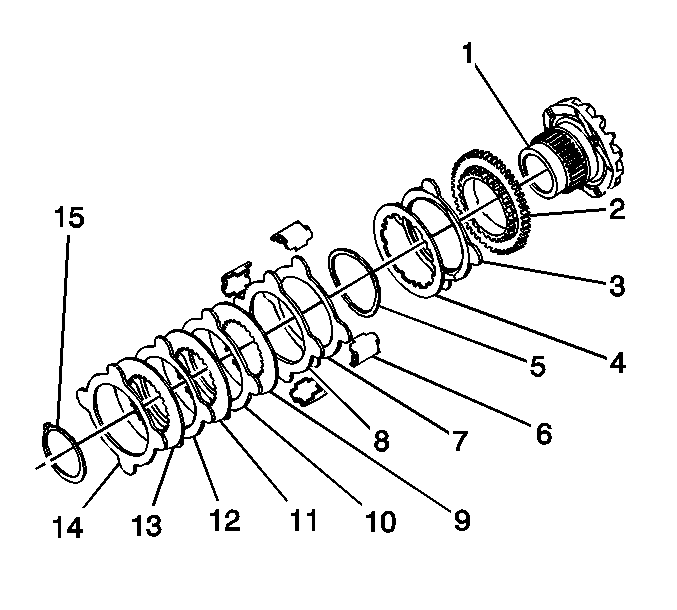
- Disassemble
the locking differential side gear cam unit and clutch disc assembly as follows:
| 3.1. | Remove the clutch discs and the splined discs (7-14). |
| 3.2. | Remove the wave washer (5). |
| 3.3. | Remove the fuse disc (4). |
| 3.4. | Remove the carbon eared disc (3). |
| 3.5. | Disassemble the cam plate (2) from the cam side gear (1). |
Locking Differential Cam Unit Disassemble 9.5 Inch Axle
Tools Required
| • | J 45232
Differential
Bearing Adjuster Needle Bearing Installer - LH |
- Measure and record the overall length of the gear assembly from the front
of the gear to the thrust sleeve, including the side gear thrust washer.
- Remove the guide clips.

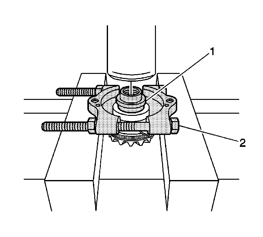
- Remove the thrust sleeve using the
J 22912-O1
(2) and the
J 45232
(1), if necessary, and a hydraulic press.

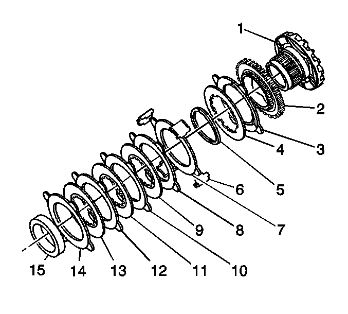
- Disassemble the locking differential side
gear cam unit and clutch disc assembly as follows:
| 4.1. | Remove the clutch discs and the splined discs (7-14). |
| 4.2. | Remove the wave washer (5). |
| 4.3. | Remove the fuse disc (4). |
| 4.4. | Remove the carbon eared disc (3). |
| 4.5. | Disassemble the cam plate (2) from the cam side gear (1). |


