Transmission Housing Oil Seal Replacement Rear Wheel Drive
Removal Procedure
- Raise the vehicle. Refer to Lifting and Jacking the Vehicle in General Information.
- Remove the rear propeller shaft. Refer to Two-Piece Propeller Shaft Replacement or One-Piece Propeller Shaft Replacement in Propeller Shaft.
- If the vehicle is equipped with a P model NV4500 transmission, perform the following:
- If the vehicle is equipped with a C model NV4500 transmission, perform the following:
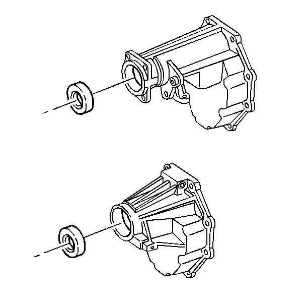
- Remove the rear oil seal from the extension housing.
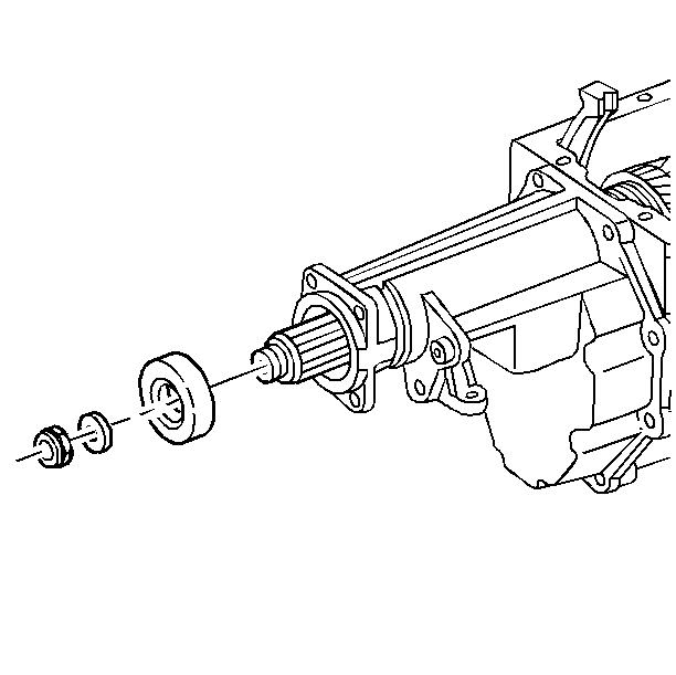
| • | Remove the mainshaft nut. |
| • | Remove the washer. |
| • | Remove the spline seal. |
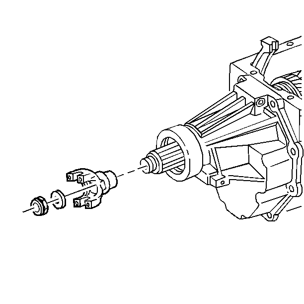
| • | Remove the mainshaft nut. |
| • | Remove the washer. |
| • | Remove the yoke. |
Installation Procedure
Tools Required
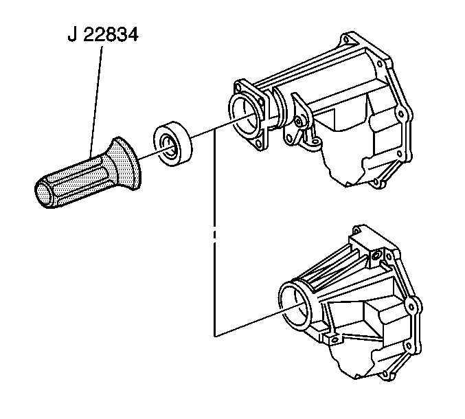
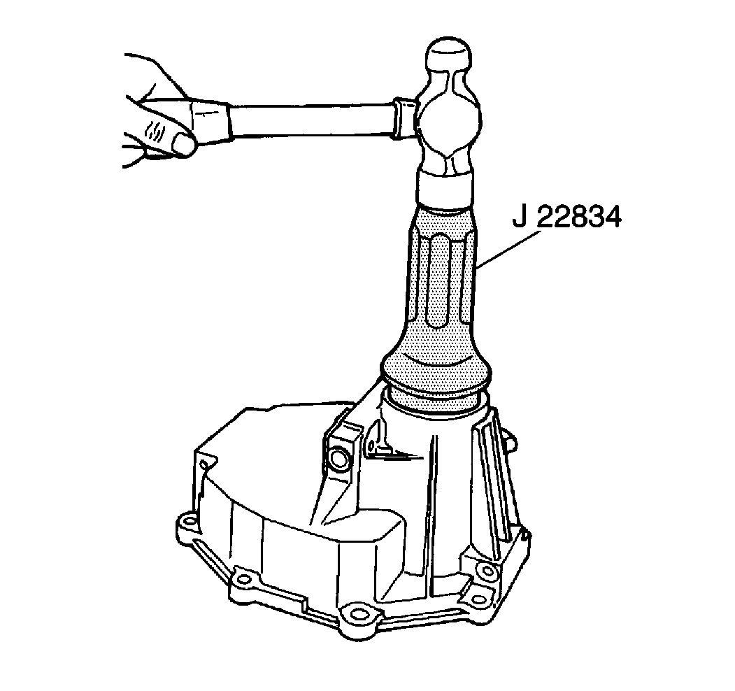
J 22834-A Extension Housing Seal Installer
- Using J 22834-A install the new rear oil seal into the extension housing.
- Ensure J 22834-A is centered on the seal during installation.
- If the vehicle is equipped with a P model NV4500 transmission, perform the following:
- If the vehicle is equipped with a C model NV4500 transmission, perform the following:
- Install the rear propeller shaft. Refer to Two-Piece Propeller Shaft Replacement or One-Piece Propeller Shaft Replacement in Propeller Shaft.
- Check the transmission oil level. Refer to Fluid Replacement .
- Lower the vehicle.

| • | Install the spline seal. |
| • | Install the washer. |
| • | Install the mainshaft nut. |

| • | Install the yoke. |
| • | Install the washer. |
| • | Install the mainshaft nut. |
Transmission Housing Oil Seal Replacement Four Wheel Drive
Removal Procedure
Tools Required
J 38805 Main Shaft Nut Socket
- Raise the vehicle. Refer to Lifting and Jacking the Vehicle in General Information.
- Remove the rear propeller shaft. Refer to Two-Piece Propeller Shaft Replacement or One-Piece Propeller Shaft Replacement in Propeller Shaft.
- Remove the transfer case. Refer to Transfer Case Replacement in NV246 Automatic Transfer case or Transfer Case Replacement in NV261 Manual Transfer Case.
- Perform the following:
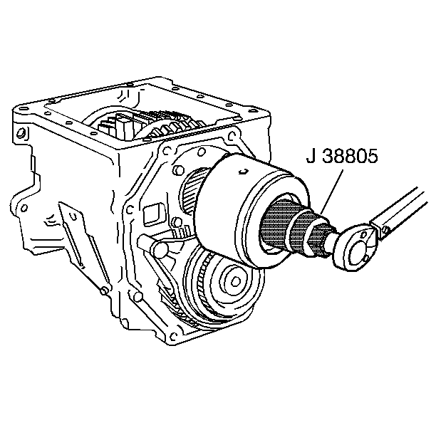
- Remove the mainshaft nut and washer from the mainshaft using J 38805 .
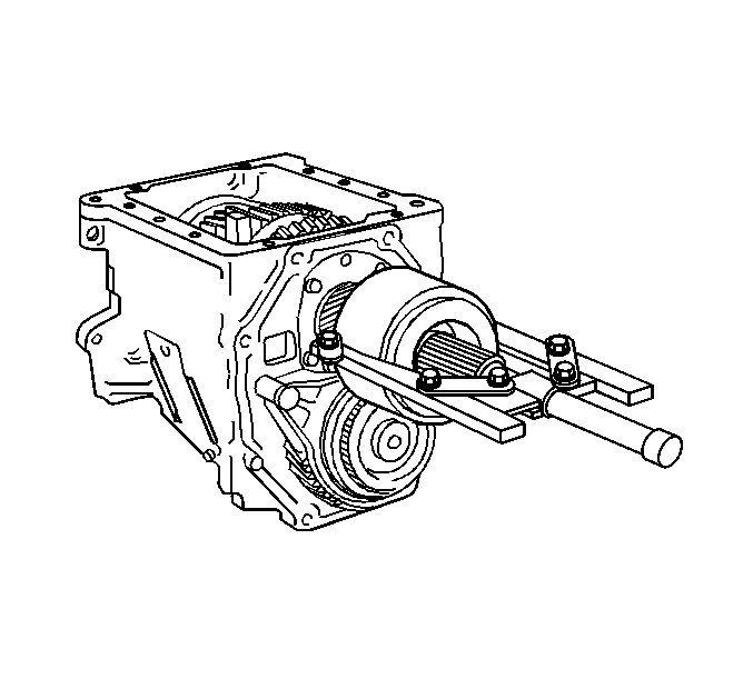
- Remove the vibration damper from the mainshaft using a suitable gear puller.
- Mark the main drive gear bearing retainer and case for alignment.
- Remove four bolts securing the main drive gear bearing retainer.
- Remove the main drive gear bearing retainer.
- Remove the seal from the main drive gear bearing retainer.
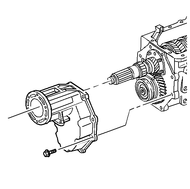
| • | Remove the bolts securing the extension housing to the transmission. |
| • | Remove the extension housing from the transmission. |
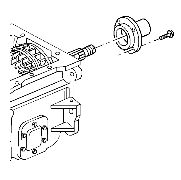
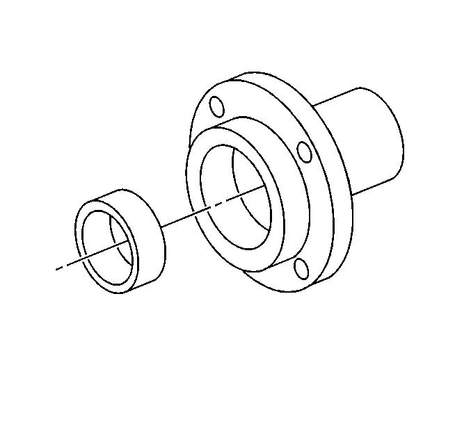
Installation Procedure
Tools Required
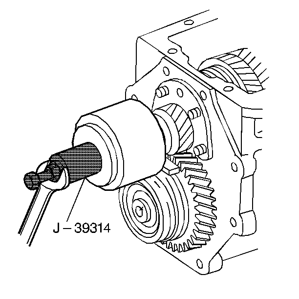
J 38807 Rear Drive Gear Bearing Retainer Seal Installer J 39314 Vibration Damper Installer J 38805 Main Shaft Nut Socket
- Install the seal into the main drive gear bearing retainer using J 38807 .
- Apply sealant GM P/N 12346004 to the main drive gear bearing retainer mating surface.
- Install the main drive gear bearing retainer to the transmission with four bolts.
- Install the vibration damper to the mainshaft using J 39314 .
- Install the mainshaft washer and nut using J 38805 .
- Install the extension housing to the transmission with eight bolts.
- Install the transfer case. Refer to Transfer Case Replacement in NV246 Automatic Transfer case or Transfer Case Replacement in NV261 Manual Transfer Case.
- Install the rear propeller shaft. Refer to Two-Piece Propeller Shaft Replacement or One-Piece Propeller Shaft Replacement in Propeller Shaft.
- Check the transmission oil level. Refer to Fluid Replacement .
- Lower the vehicle.
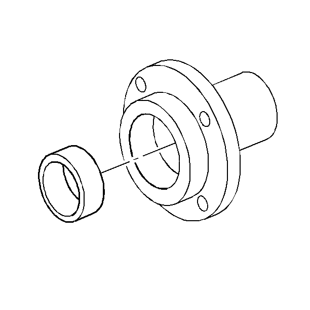
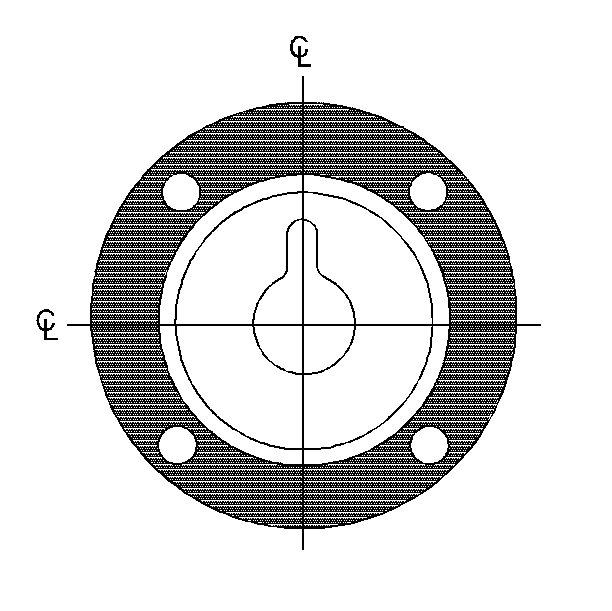
Ensure the oil hole on the main drive gear bearing retainer is not covered with the sealant.

Notice: Use the correct fastener in the correct location. Replacement fasteners must be the correct part number for that application. Fasteners requiring replacement or fasteners requiring the use of thread locking compound or sealant are identified in the service procedure. Do not use paints, lubricants, or corrosion inhibitors on fasteners or fastener joint surfaces unless specified. These coatings affect fastener torque and joint clamping force and may damage the fastener. Use the correct tightening sequence and specifications when installing fasteners in order to avoid damage to parts and systems.
Tighten
Tighten the bolts to 35 N·m (26 lb ft).

Tighten
Tighten the nut to 441 N·m (325 lb ft).

Tighten
Tighten the nut to 54 N·m (40 lb ft).
