Controls
The heater control head in the instrument panel contains the following controls:
| • | A blower speed control knob |
| • | A desired operation selection knob |
| • | An air temperature control knob |
These controls illuminate when the headlamps are ON. The instrument panel lighting circuit provides the voltage. The dimmer control of the headlamp switch controls the brightness of the dial illumination.
Temperature Knob
The temperature knob operates an electronic actuator. When the temperature knob is in the COLD (blue) position, the air delivered by the HVAC system is unheated. When the temperature knob is in the HOT (red) position, all of the air that passes through the heater module is heated before the air discharges. Intermediate positions of the temperature knob result in a mixture of heated and unheated air in order to provide more moderate air temperatures.
When you move the temperature knob away from the cold position, the temperature valve moves away from the heater core in order to allow for some air flow through the heater core. The more you move the temperature knob toward the hot position, the greater the air flow through the heater core. Heating a greater portion of the airflow in this manner results in a warmer discharge of air from the outlets.
When the temperature knob is in the full hot position, the temperature valve blocks off the passage that allows the air to bypass the heater core. This causes all of the airflow to go through the heater core for maximum heating. This method of temperature control provides a very rapid response to any change in the temperature selection throughout the entire range when the engine is warmed up.
An electric motor, not a cable system, controls the temperature door.
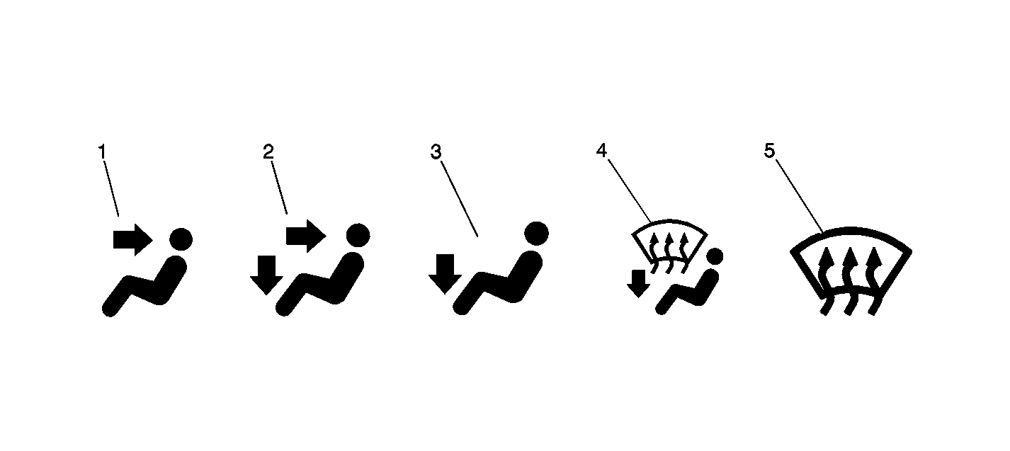
Mode Knob
The mode knob operates an electronic actuator. Each actuator operates a valve, a door-like hinge deflector, that routes the airflow to the various outlets of the heater system.
The mode knob has the following positions:

