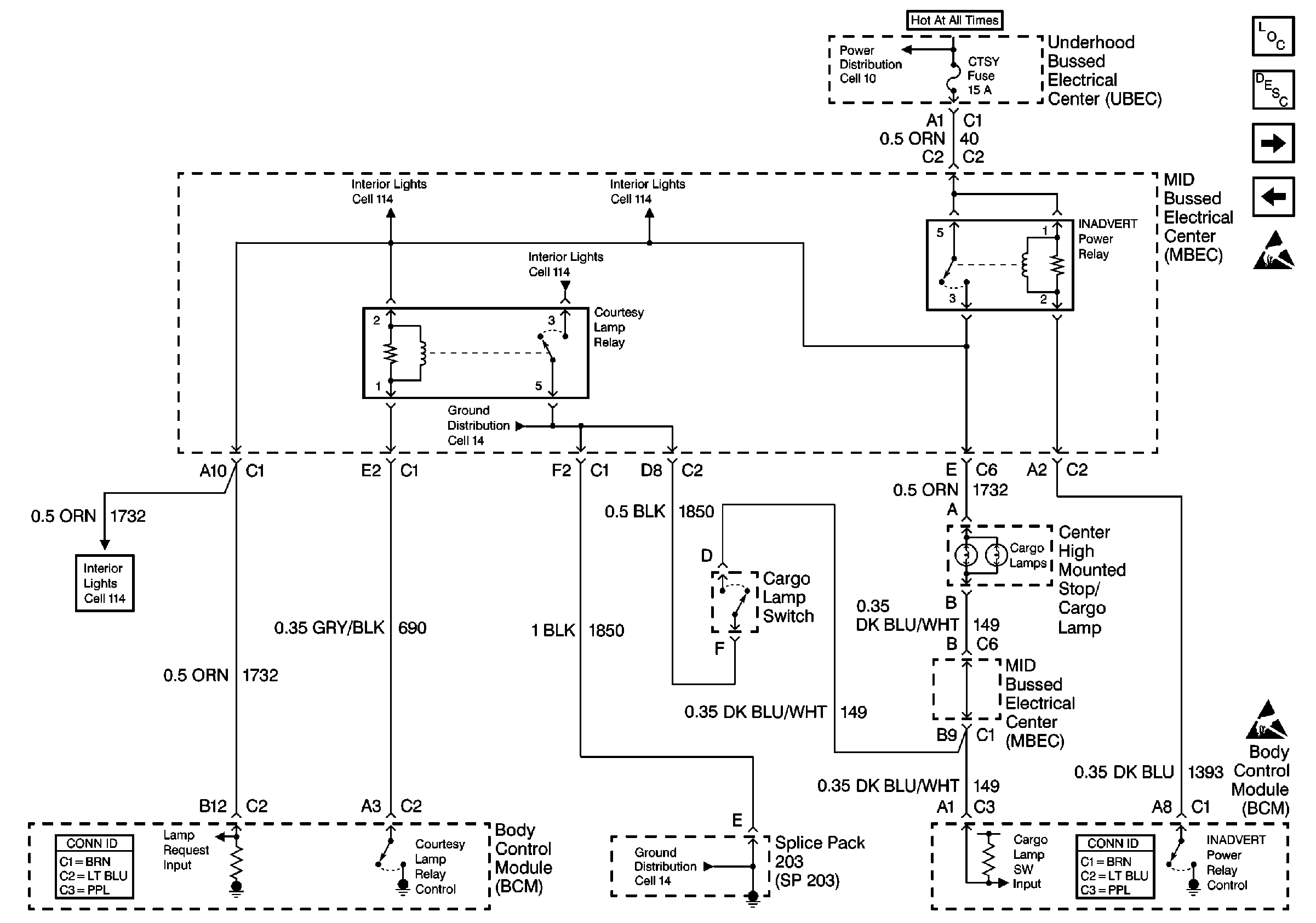
For a full page schematic, refer to
Cell 51: Inadvertent Power Relay, Courtesy Lamp Relay

.
Circuit Description
The battery rundown protection function allows the body control module (BCM) to disable the courtesy lamps, the cargo lamps and the underhood lamp 40 minutes after the ignition switch is turned OFF. The BCM monitors the output of the inadvertent power relay on CKT 1732.
Conditions for Setting the DTC
| • | When the BCM commands the inadvertent power relay on via CKT 1393 and CKT 1732 has an absence of voltage to the BCM, DTC B1480 will set. |
| • | The system voltage must be between 9.0-16.0 volts. |
| • | The above conditions must be met for 0.5 seconds. |
Action Taken When the DTC Sets
The following lamps will be disabled:
| • | The dome |
| • | The glove box |
| • | The reading |
| • | The underhood |
Conditions for Clearing the MIL/DTC
| • | This DTC will clear after the condition for setting the fault is corrected. |
| • | A history DTC will clear after 100 consecutive ignition cycles without a fault present. |
| • | Use a scan tool in order to clear the history DTC(s). |
Diagnostic Aids
Important: Use the appropriate probe from the connector test adapter kitJ 35616 for any probing of the bussed electrical centers (BECs) in this table in order to avoid damage to the BECs.
| • | Always diagnose the first DTC listed on the scan tool. |
| • | The scan tool must display DTC B1480 as a current code before performing diagnostics. |
| • | Perform a visual inspection for loose or poor connections at all related components. |
| • | Check for an open in CKT 40 or an open CTSY LP fuse. |
| • | Refer to Testing for Electrical Intermittents in Wiring Systems. |
Test Description
Step number(s) below refer to the same step number(s) in the Diagnostic Table
-
This step tests the CTSY LP fuse.
-
This step inspects the control circuit of the inadvertent power relay, inadvertent power relay and the CTSY LP fuse.
-
This step determines if CKT 1732 is open or the BCM is unable to monitor voltage on circuit 1732.
-
This step determines if CKT 40 is open.
-
This step checks if CKT 1393 is open between the inadvertent power relay and the BCM.
-
This step determines if CKT 1732 is open between the mid bussed electrical center (MBEC) and the BCM.
Step | Action | Value(s) | Yes | No |
|---|---|---|---|---|
1 | Was the BCM Diagnostic System Check performed? | -- | ||
2 | Turn dome light switch ON (defeat switch OFF). Test both sides of the CTSY fuse with a test lamp to ground. Does the test lamp light on both sides of the fuse? | -- | ||
3 | Does the test lamp light on either side of the fuse? | -- | ||
4 | Locate and repair the short to ground in CKT 40 (ORN) or CKT 1732 (ORN). Is the repair complete? | -- | -- | |
5 | Replace the underhood bussed electrical center (UBEC). Is the repair complete? | -- | -- | |
6 |
Does the scan tool display DTC 1480 as current? | -- | ||
7 |
Does the J 39200 DMM display battery voltage? | -- | ||
8 |
Does the J 39200 DMM display battery voltage at both cavities? | -- | ||
9 |
Is the resistance within the specified range? | 0-5 ohms | ||
10 |
Is the resistance within the specified range? | 0-5ohms | ||
11 | Locate and repair open in CKT 1393 (DK BLU) between the BCM and the inadvertent power relay (MBEC). Is the repair complete? | -- | -- | |
12 | Locate and repair open in CKT 1732 (ORN) between the BCM and the inadvertent power relay (MBEC). Is the repair complete? | -- | -- | |
13 | Locate and repair open in CKT 40 (ORN) between inadvertent power relay and the UBEC. Is the repair complete? | -- | -- | |
14 | Replace the inadvertent power relay. Is the repair complete? | -- | -- | |
15 |
Is the repair complete? | -- | System OK | -- |
16 | Clear the DTCs. Refer to Clearing DTCs . Is the repair complete? | -- | System OK | -- |
