Door Service Front
Removal Procedure-Body
- Remove the door from the body.
- Remove any excess sealer surrounding the existing hinge and scribe the location of the hinge on the hinge pillar.
- Lightly hand-sand the existing hinge with 100 grit or finer sandpaper in order to locate the 4 welds that attach the hinge to the pillar.
- Center punch each of the 4 weld marks on the original hinge.
- Drill through the hinge only (2), at each punch location. Use a 13 mm (½ in) rotabroach hole saw (3) or the equivalent.
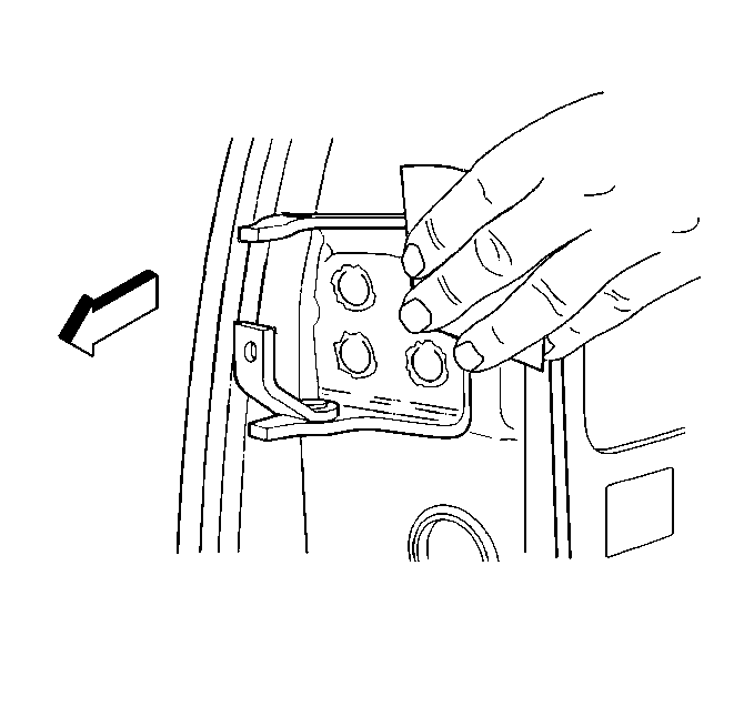
- Remove the hinge. If necessary, use a chisel in order to separate the hinge from the pillar.
- Remove all of the remaining weld from the pillar surface in order to ensure a flush fit of the service hinge.
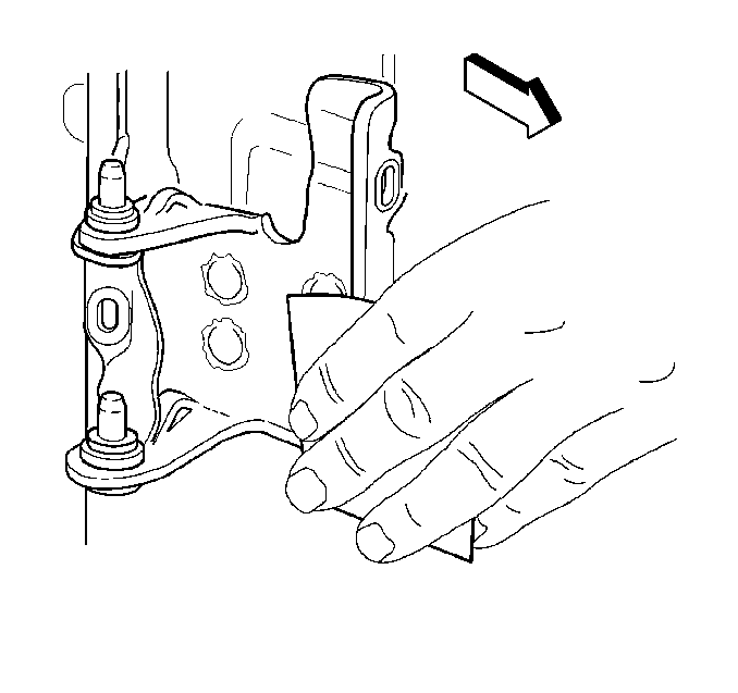
Important: Punch the center of the weld so that as much of the weld as possible is removed during the drilling.
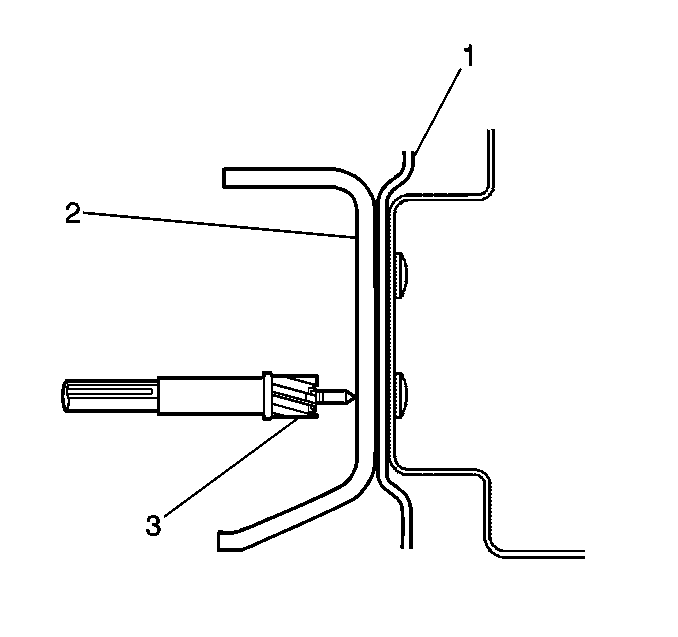
Important: Do not drill into the hinge pillar (1).
Installation Procedure
- Repair any damage done to the pillar during the drilling or the removal.
- Position the service hinge within the scribe marks on the pillar.
- Center punch each stud location on the hinge pillar according to the service hinge.
- Drill a 3 mm (1/8 in) pilot hole at each center punch location.
- Drill an 11.5 mm (29/64 in) hole at the pilot locations for the studs (1).
- Clean and prepare all of the bare metal surfaces.
- Apply approved anti-corrosion primer.
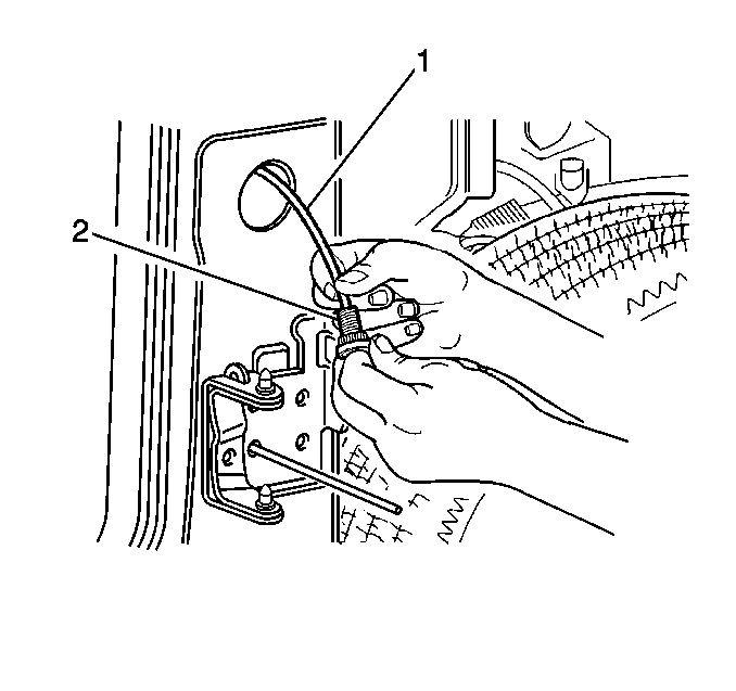
- Feed fish wire (1), GM P/N 15017229 or the equivalent, through the hinge, the hinge stud hole and out of the conduit hole in the pillar.
- Install the stud (2), GM P/N 15017230, supplied with the service hinge into the wire end. Pull the stud into position.
- Hold the stud in position with the hinge and remove the fish wire.
- Draw the stud tight through the pillar. Use the nuts (1) (GM P/N 11516746) supplied.
- Repeat steps 7-10 on the remaining stud locations.
- Remove each service nut.
- Apply a full-bodied caulk to the entire hinge mounting surface in order to ensure a proper seal.
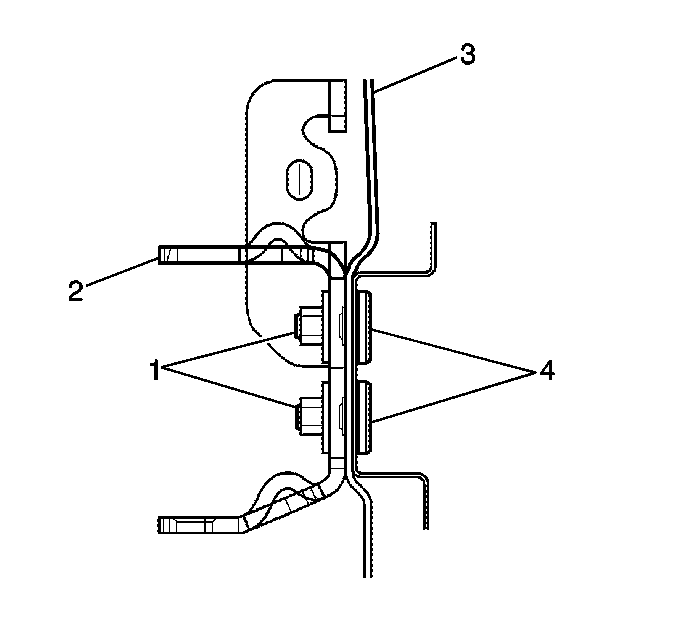
- Install the hinge (2) to the pillar (3). Use the supplied nuts.
- Clean and prepare all of the surfaces as necessary for refinishing.
- Apply the sealers.
- Refinish the surfaces as necessary.
- Install and align all of the related panels and the components.
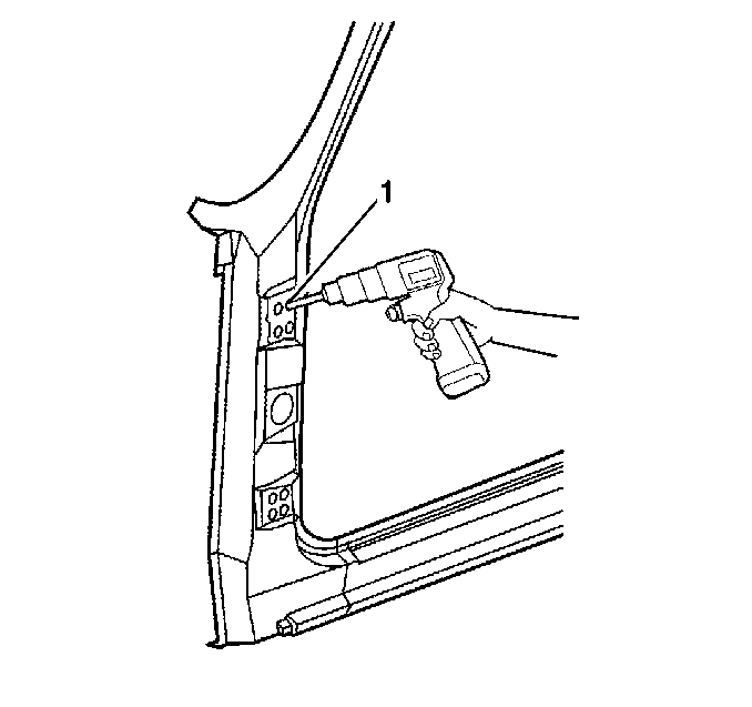
Important: Drill must be exact size.
Important: Prior to refinishing, refer to GM 4901MD-99 Refinish Manual for recommended products. Do not combine paint systems. Refer to paint manufacturer's recommendations.
Notice: Use the correct fastener in the correct location. Replacement fasteners must be the correct part number for that application. Fasteners requiring replacement or fasteners requiring the use of thread locking compound or sealant are identified in the service procedure. Do not use paints, lubricants, or corrosion inhibitors on fasteners or fastener joint surfaces unless specified. These coatings affect fastener torque and joint clamping force and may damage the fastener. Use the correct tightening sequence and specifications when installing fasteners in order to avoid damage to parts and systems.
Tighten
Torque the hinge to the pillar nuts to 25 N·m (18 ft lb).
Removal Procedure-Door
- Remove the door from the body.
- Remove any excess sealer surrounding the hinge and scribe the location of the hinge on the door.
- Lightly hand-sand the existing body hinge with 100 grit or finer sandpaper in order to locate the 4 welds that attach the hinge to the door.
- Center punch each of the 4 weld marks on the original hinge base.
- Drill through hinge base only (2) at the punch location. Use a 13 mm (½ in) rotabroach hole saw (3) or the equivalent.
- Remove hinge. If necessary, use a chisel to separate the hinge from the door.
- Remove all of the remaining weld from the door surface in order to ensure a flush fit of the service hinge.
Important: Punch the center of the weld so that as much of the weld is removed during the drilling as possible.
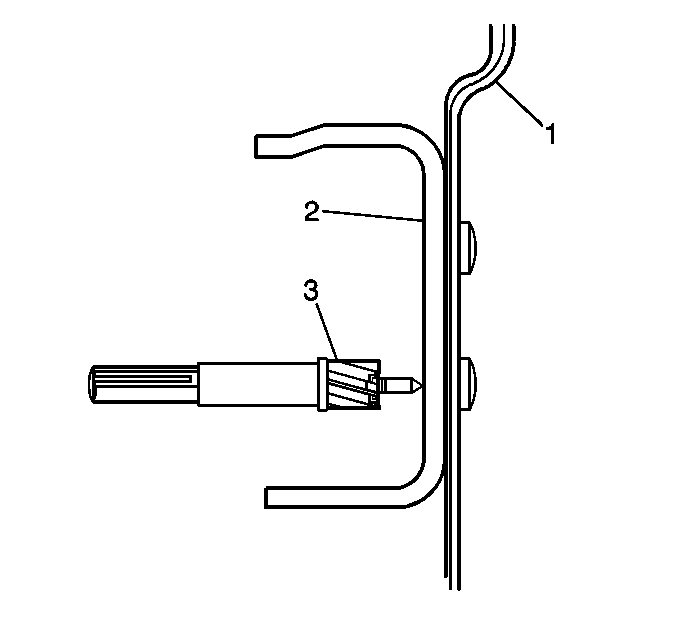
Important: Do not drill into the door (1).
Installation Procedure
- Repair any damage done to door during the drilling or the removal.
- Clean and prepare the backing plate mounting surfaces in order to ensure a flush fit of the backing plate.
- Position the service hinge within the scribe marks on the door.
- Center punch each hole location on the door according to the service hinge.
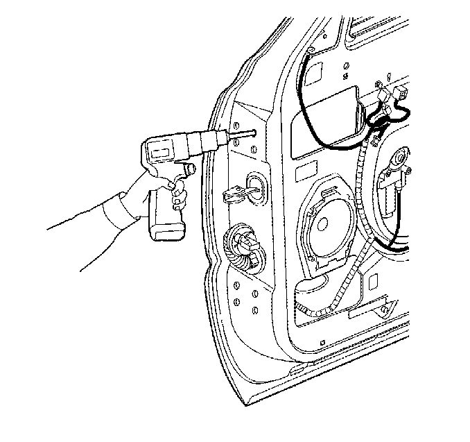
- Drill a 3 mm (1/8 in) pilot hole at each center punch location.
- Drill a 13 mm (1/2 in) hole at the pilot locations.
- Clean and prepare all of the bare metal surfaces.
- Apply approved anti-corrosion primer.
- Apply full-bodied caulk to the entire hinge mounting surface in order to ensure a proper seal.
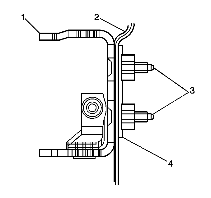
- Align the hinge (1) and the backing plate (4) with the holes in the door (2).
- Install the bolts (3).
- Apply the sealers.
- Refinish the metal surfaces as necessary.
- Install and align all of the related panels and the components.
Important: Prior to refinishing, refer to GM 4901MD-98 Refinish Manual for recommended products. Do not combine paint systems. Refer to paint manufacturer's recommendations.
Notice: Use the correct fastener in the correct location. Replacement fasteners must be the correct part number for that application. Fasteners requiring replacement or fasteners requiring the use of thread locking compound or sealant are identified in the service procedure. Do not use paints, lubricants, or corrosion inhibitors on fasteners or fastener joint surfaces unless specified. These coatings affect fastener torque and joint clamping force and may damage the fastener. Use the correct tightening sequence and specifications when installing fasteners in order to avoid damage to parts and systems.
Tighten
Tighten the bolts to 25 N·m (18 ft lb).
