Tech - Steering or Front End Induced Vibration (Inst/Reinforce Strng/Susp Comp)

| Subject: | Steering or Front End Road Induced Vibration (Install and Reinforce Revised Steering and Suspension Components) |
| Models: | 1999-2000 Chevrolet and GMC C1500 Pickup Trucks (Silverado and Sierra) |
Built Prior to the Following VINs
Plant | Body Series | VIN |
|---|---|---|
Fort Wayne, IN | C15703 | 1GCEC14V7YZ243861 |
C15753 | 1GTEC19T8YZ244020 | |
C15903 | 1GCEC14T4YZ245211 | |
Pontiac, MI | C15903 | 1GCEC14V4YE279931 |
C15953 | 1GCEC19V1YE277451 | |
Oshawa, ON | C15753 | 2GCEC19VXY1264957 |
Important: Canadian dealers require PRIOR District Service Manager approval to apply this bulletin.
Condition
Some customers may comment on a steering wheel or front end vibration.
Cause
Several components in the front end steering and suspension work in unison to isolate the driver from road irregularities and from road/tire induced vibration. If any of these components are not working effectively, it will affect the other components of the suspension and steering system. Tire and road vibrations may be transmitted to the passenger compartment and steering through the rack and pinion unit. Additionally, the mounting points of the steering rack on the front frame crossmember may be amplifying any road vibrations.
Correction
In order to dampen unwanted vibration from the steering wheel, the following revisions must be performed:
| • | The tires must be in accordance with Corporate Bulletin Number 99-03-09-002 published August, 1999. |
| • | The steering rack must be replaced with a revised rack. |
| • | The left front steering rack mounting point must be reinforced. |
| • | The lower control arms must be replaced with units incorporating a revised bushing. |
| • | The power steering (PS) pump metering valve must be replaced with a revised fitting. |
Use the following procedure to replace the required components. Use the part numbers listed below.
Notice: All components listed above must be replaced in order to correct the customer concern. Incremental replacements will adversely affect the handling and ride qualities of the vehicle. All components of the repair must be in place before the vehicle is returned to the customer.
- Raise the vehicle. Refer to the General Information subsection of the Service Manual for information on lifting and jacking the vehicle.
- Remove the tire and wheel assemblies.
- Remove the front skid plate.
- Remove the rear skid plate.
- Remove the high and low pressure power steering lines from the rack and pinion unit.
- Remove the steering intermediate shaft pinch bolt.
- Remove the right and left outer tie rod end nuts.
- Remove the tie rod ends nuts from the steering knuckles.
- Remove the two nuts retaining the rack and pinion unit. Remove and rack and pinion unit from the vehicle.
- Remove and transfer the outer tie rod ends to the revised steering gear.
- Remove the two long bolts that retain the rack using a pry bar to slightly move the position of the anti-sway bar. This will allow removal of the steering rack retaining bolts through the crossmember.
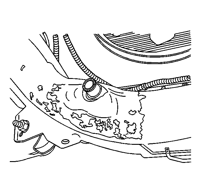
- Remove the undercoating from around the left side rack and pinion mount with solvent.
- Lightly grind the area around the left mount.
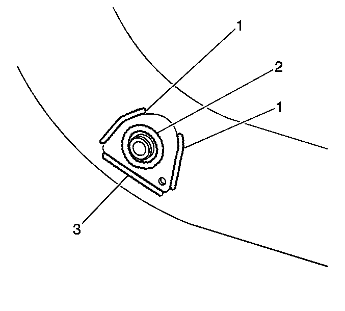
- In order to obtain an effective weld for this repair, you must follow the welding pattern diagram. The most effective way of welding this reinforcement is to quickly tack the three sides of the reinforcement first. This method will keep all sides of the reinforcement in contact with the frame crossmember throughout the welding operation. If one whole side of the reinforcement is welded without first tacking the edges, the patch may warp. If the reinforcement plate warps, it will be difficult to obtain as accurate a weld. A warped reinforcement plate will also increase the size of the gap that must be sealed later in this procedure.
- The finished weld must consist of four welded beads. Two beads along the side of the reinforcement (1) must be 80 mm (3.20 in). The bead along the lower edge (3) must be at least 90 mm (3.60 in). The final weld (2) should be a continuous bead around the center of the reinforcement to the mounting post on the crossmember. A correct weld bead should measure 120 mm (4.80 in) around the post. Let the weld area cool.
- Coat the reinforcement plate and the bare portion of the frame crossmember with a self-etching primer. Allow the primer to flash off its solvent.
- Apply a heavy-bodied seam sealer, such as 3M Ultrapro Autobody Sealant (P/N 08302) or equivalent, to all edges of the reinforcement. The P/N for the 3M Sealer is for a clear style. Any color is acceptable for this repair. Create a seal along the edges and around the center mount coming through the plate. A good seal will prevent moisture from accumulating between the frame crossmember and the back side of the welded reinforcement.
- As soon as the sealer skins-over, you can apply an undercoating. Apply a spray-on black, rubberized undercoating to the reinforcement and the crossmember. Overlap the original coating in order to provide an effective corrosion protection.
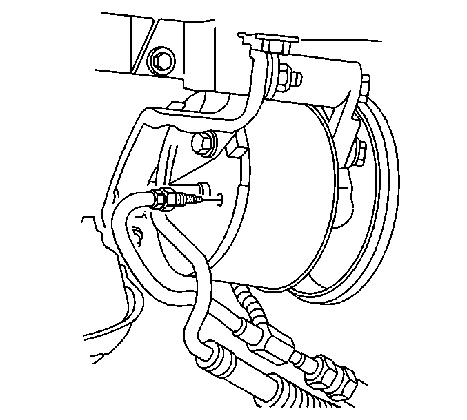
- Remove the high-pressure PS fluid line from the rear of the PS pump.
- Remove the brass PS pump-metering valve.
- Install the revised metering valve to the PS pump.
- Install the PS fluid high-pressure line to the pump.
- Remove the front upper shock mounts.
Tighten
Tighten the tie rod end jam nuts to 68 N·m (50 lb ft).
Left Front Frame Crossmember Steering Rack Attachment Point

| • | Extend the grinding area to at least a 101 mm (4 in) area around the left side rack mounting point. |
| • | Remove all underbody coating around the reinforcement plate in order to obtain the strongest weld possible. In addition, some area around the reinforcement must be cleared of undercoating in order to prevent the possibility of the coating "flashing". |
Caution: The underbody coating on the frame will burn if exposed to the extreme heat of welding. The coating may ignite and/or flash suddenly. Avoid direct contact of the welding torch to the underbody coating. Always remove the coating so that sufficient area is free of coating for the welding operation to be performed without risk of igniting the coating. Avoid inhalation of fumes from any over-heated or burning underbody coating
Crossmember Reinforcement Plate Welding Pattern

Important: It is essential that a primer coating and effective seal be created around the reinforcement. This creates a corrosion barrier for the mating surface of the plate and frame crossmember.
Power Steering Pump Metering Valve

Tighten
Tighten the valve to 33 N·m (24 lb ft).
Tighten
Tighten the line fitting to 28 N·m (20 lb ft).
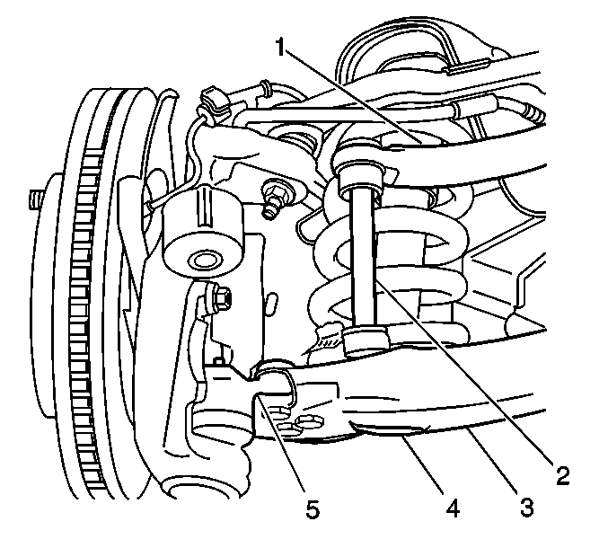
Front Suspension Components

Parts Information
Part Number | Description |
|---|---|
26087761 | Gear Kit - Steering (Reman) |
26089167 | Fitting, Power Steering Pump |
15764194 | Reinforcement, Front C/Member |
12477633 | Bushing Assembly - Frt Lwr Cont Arm (LH) |
12477634 | Bushing Assembly - Frt Lwr Cont Arm (RH) |
11516073 | Nut, Tie Rod (2 per vehicle) |
11516133 | Nut, Frt Lwr Cont Arm (4 per vehicle) |
11517861 | Bolt/Nut, Steering Rack Mounting (2 per vehicle) |
15709061 | Bolt/Screw - M8 X 1.25 X 16 |
15017021 | Washer, S/Gear Rack Mounting (2 per vehicle) |
11501869 | Washer - M8 |
Parts are currently available from GMSPO.
Warranty Information
For vehicles repaired under warranty, use:
Labor Operation | Description | Labor Time |
|---|---|---|
E9850 | Steering Wheel Vibration Correction | 3.8 hrs |
This is a unique labor operation for use only with this bulletin. This number will not be published in the Labor Time Guide. | ||
