Clunk Noise from Front of Vehicle (Replace Left Front Mount Bracket)

| Subject: | Clunk Noise From Front of Vehicle (Replace Left Front Mount Bracket, Add Reinforcements to Frame and Bracket) |
| Models: | 1999 Chevrolet and GMC K1500 Series Pickup Models (Silverado and Sierra) |
Condition
Some customers may comment on a clunk noise coming from the front of the vehicle. Vehicles exposed to extreme off-road conditions or snow plowing are more prone to develop this condition.
Cause
The condition may be caused by a left front axle mount bracket crack at the frame due to an area of high stress.
Correction
A differential carrier support kit has been developed to distribute the load of the axle away from the area of high stress where crack initiation may occur. Replace the left front axle mount bracket. Add reinforcements to the frame and bracket. Use the following service procedure.
- Disconnect the negative terminal from the battery.
- Raise the vehicle. Place a jack or utility stands at the rear of the vehicle.
- Remove both of the front tire and wheel assemblies.
- Remove the differential carrier shield.
- Reference mark the relationship of the propeller shaft to the front drive axle pinion yoke.
- Remove the yoke retainer bolts and the yoke retainers from the front axle pinion yoke.
- Disconnect the propeller shaft from the front axle pinion yoke. Wrap the bearing caps with tape in order to prevent the loss of bearing rollers.
- Support the propeller shaft and move out of the way as necessary.
- Remove the bolts securing both wheel drive shaft inboard flanges to the output shaft flanges.
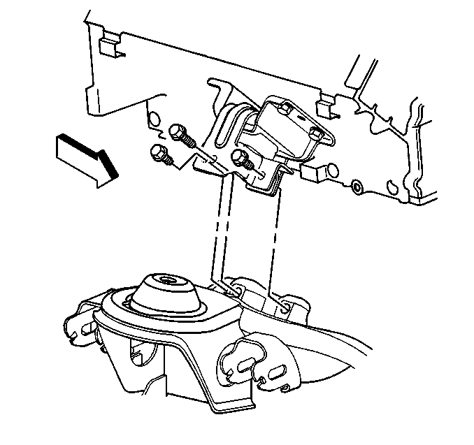
- Remove the inner axle housing nuts (2) from the bracket (1).
- Disconnect the electrical connections and the wiring harness retainers from the front differential carrier.
- Disconnect the vent hose.
- Remove the differential carrier assembly lower mounting bolt (3) and nut (4).
- Remove the idler arm ball stud nut (10) and disconnect the idler arm (1) from the relay rod (9) using the J 24319-B.
- Remove the pitman arm ball stud nut (8) and disconnect the pitman arm (2) from the relay rod (9) using the J 24319-B.
- Attach a transmission jack to the carrier assembly.
- Remove the differential carrier assembly upper mounting bolt (1) and nut (2).
- Remove the differential carrier assembly from the vehicle.
- Remove the steering gear frame bolts and reposition the steering gear.
- Remove the stands and lower the vehicle.
- Remove the bolts retaining the RH and LH upper engine mount to the lower engine mount.
- Raise the vehicle. Place a jack or utility stands at the rear of the vehicle.
- Raise and support the engine with a suitable jack.
- Remove the LH lower engine mount bracket through bolts and bracket.
- Block the engine in the raised position using a piece of wood between the oil pan and crossmember.
- Remove the support from the engine.
- Clean the axle mounting bracket area with a wire brush in order to determine the full extent of the cracks.
- Remove the existing differential carrier bracket from the sidemember using a reciprocating saw and cut-off wheel.
- Grind off any remaining metal and welds from the sidemember.
- Clean off the area using an air gun.
- Remove all the underbody coating from the sidemember around the repair area using a solvent. In addition, remove the underbody coating from the top of the sidemember in order to prevent run down and weld contamination.
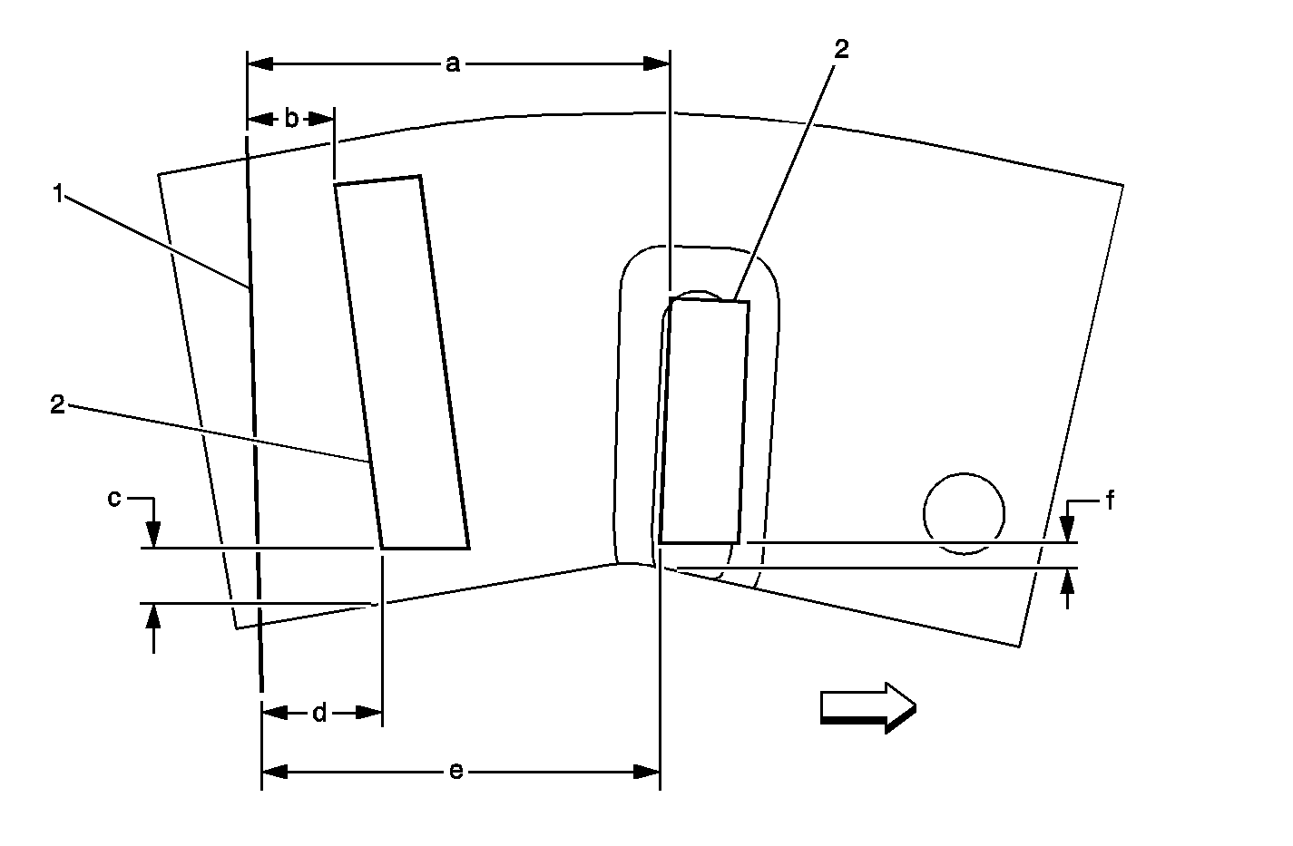
- Repair the cracks in the sidemember.
Notice: When removing the propeller shaft, do not attempt to remove the shaft by pounding on the yoke ears or using a tool between the yoke and the universal joint. If the propeller shaft is removed by using such means, the injection joints may fracture and lead to premature failure of the joint.
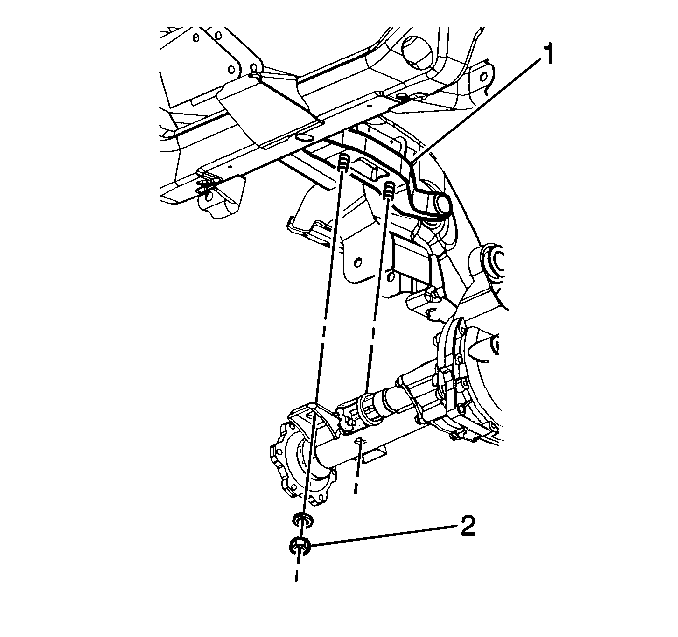
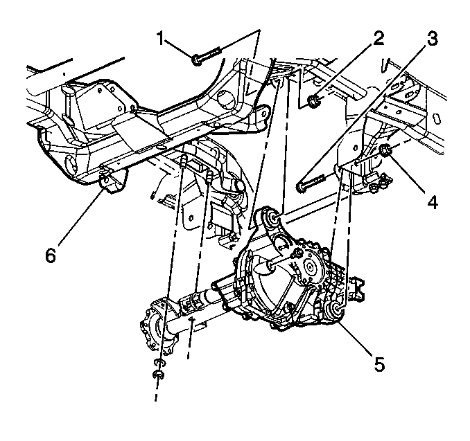
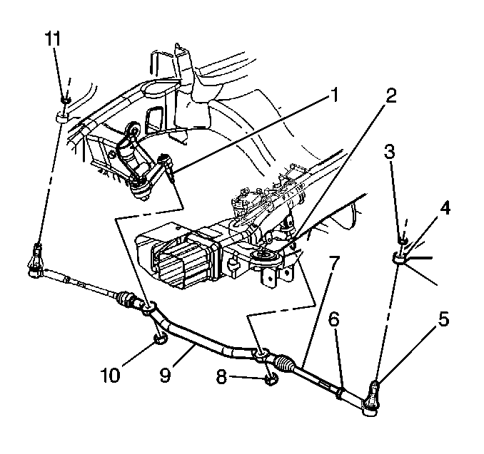
Important: Do not reuse the idler arm and pitman arm ball stud nuts.
Notice: Do not hammer on the pitman arm, pitman arm shaft or puller. Damage to the pitman arm or steering gear may result.
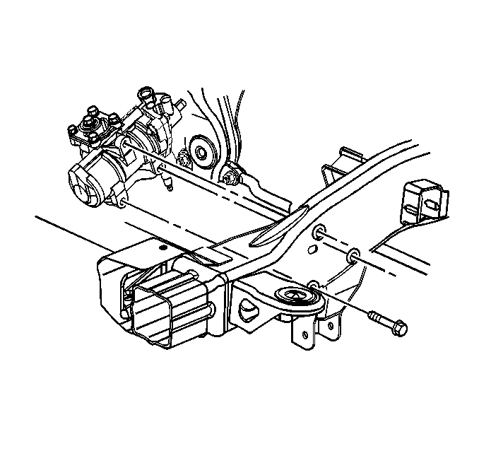
Caution: The underbody coating on the frame will burn if exposed to the extreme of welding. The coating may ignite and/or flash suddenly. Avoid direct contact of the torch to the underbody coating. Always remove the coating so that sufficient area is free of coating for the welding operation to be performed without risk of igniting the coating. Avoid inhalation of fumes from any over-heated or burning underbody coating.
| • | Drill a 5 mm (3/16 in) stop hole at the end of all existing cracks. |
| • | Clean and "V" grind all crack edges. |
| • | Fill all cracks with weld and grind smooth, making sure all surfaces are level. |
Parts Information
Part Number | Description | Qty |
|---|---|---|
15056098 | Support Kit - Diff. Carrier | 1 |
11516074 | Nut | 2 |
Parts are currently available from GMSPO.
Warranty Information
For vehicles repaired under warranty, use:
Labor Operation | Description | Labor Time |
|---|---|---|
F2122 | Carrier Assy., Front Differential - R&R | Use published labor operation time |
Add | To Replace Left Front Axle Mount Bracket and Add Reinforcements | 2.4 hrs |
Add | To Repair Frame Cracks | 0.6 hr |
