For 1990-2009 cars only
Removal Procedure
- Raise the vehicle. Refer to Lifting and Jacking the Vehicle.
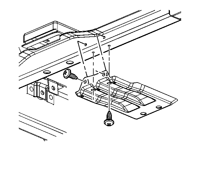
- Remove the transfer case shield. Refer to Transfer Case Shield Replacement.
- Drain the transfer case of fluid. Refer to Transfer Case Fluid Replacement.
- Remove the front propeller shaft. Refer to Front Propeller Shaft Replacement.
- Remove the rear propeller shaft.
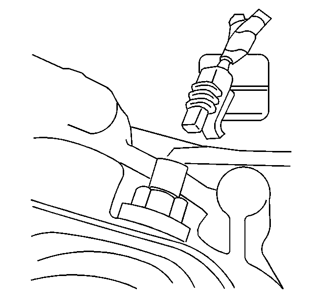
- Remove the transfer case gear indicator switch electrical connector.
- Remove the transfer case speed sensor electrical connector.
- Remove the transfer case control rod from the transfer case. Refer to Transfer Case Control Rod Replacement.
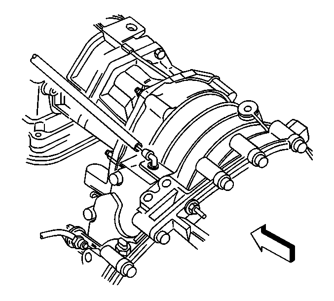
- Remove the transfer case vent hose.
- Support the transmission with a suitable transmission jack stand.
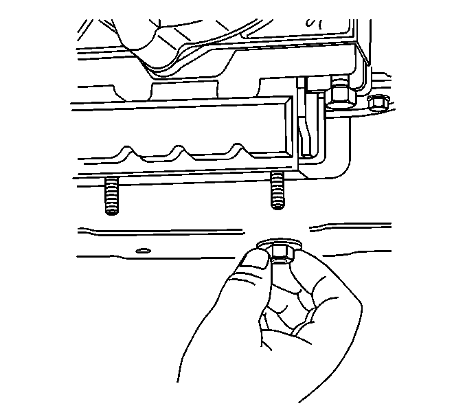
- Remove the transmission mount retaining nuts.
- Raise the transmission high enough in order to remove the transmission support
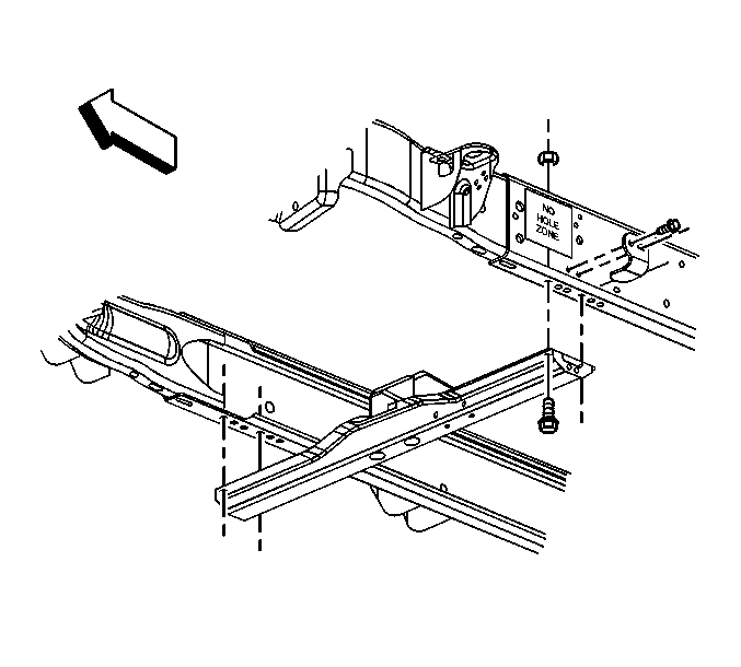
- Remove the transmission support mounting bolts.
- Remove the transmission support from the frame.
- Support the transfer case with a suitable jack stand.
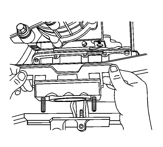
- Remove the transmission mount bolts.
- Remove the transmission mount assembly.
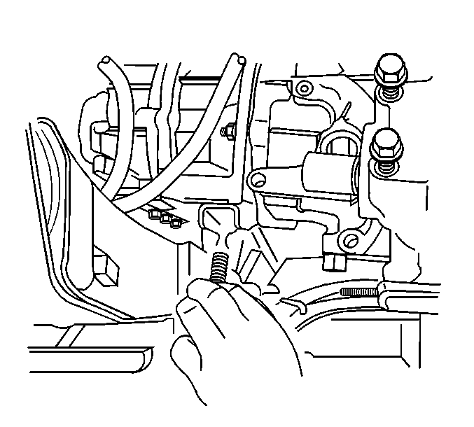
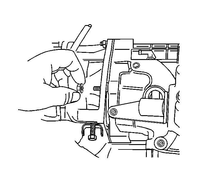
- Remove the transfer case adapter retaining nuts.
- Remove the support for the transfer case.
- Slide the transfer case straight back toward the rear of the vehicle.
- Rotate the transfer case so that the front output shaft is above the torsion bar bracket.
- Rotate the transfer case (with the input shaft slightly lowered) so that the transfer case is parallel to the torsion bar bracket.
- Lower the transfer case.
| • | For vehicles equipped with the one piece propeller shaft, refer to One-Piece Propeller Shaft Replacement. |
| • | For vehicles equipped with the two piece propeller shaft, refer to Two-Piece Propeller Shaft Replacement. |
Important: The following service procedure must be performed with the assistance from another technician.
Installation Procedure
- Apply GM /P/N 12345879 (Canadian P/N 10953511) or equivalent lubricant, meeting GM Specification 9985830 to the input shaft splines.
- Raise the transfer case into position (the transfer case should be parallel to the torsion bar bracket).
- Rotate the transfer case so that it is in line with the transfer case adapter.
- Install the transfer case to the transfer case adapter.
- Install the transfer case retaining nuts.
- Support the transfer case with a suitable jack stand.
- Install the transmission mount assembly.
- Install the transmission mount bolts.
- Install the transmission support to the frame.
- Install the transmission support mounting bolts.
- Lower the transfer case and transmission assembly on the transmission support.
- Install the transmission mount retaining nuts.
- Remove the support from the transfer case.
- Remove the transmission jack stand.
- Install the transfer case gear indicator switch electrical connector.
- Install the transfer case speed sensor electrical connector.
- Install the transfer case control rod. Refer to Transfer Case Control Rod Replacement.
- Install the transfer case vent hose.
- Install the rear propeller shaft.
- Install the front propeller shaft. Refer to Front Propeller Shaft Replacement.
- Fill the transfer case with the approved fluid. Refer to Transfer Case Fluid Replacement.
- Install the transfer case shield to the transmission support. Refer to Transfer Case Speed Sensor Replacement.
- Lower the vehicle. Refer to Lifting and Jacking the Vehicle.

Important: The following installation procedure must be performed with the assistance of another technician.
Notice: Refer to Fastener Notice in the Preface section.
Tighten
Tighten the transfer case retaining nuts to 50 N·m (36 lb ft).


Tighten
Tighten the transmission mount bolts to 47 N·m (34 lb ft).

Tighten
Tighten the transmission support mounting bolts to 70 N·m (51 lb ft).

Tighten
Tighten the transmission mount retaining nuts to 40 N·m (29 lb ft).


| • | For vehicles equipped with the one piece propeller shaft, refer to One-Piece Propeller Shaft Replacement. |
| • | For vehicles equipped with the two piece propeller shaft, refer to Two-Piece Propeller Shaft Replacement. |
