For 1990-2009 cars only
Control Valve Body Disassemble Disassembly of Control Valve Assembly
Disassembly of Control Valve Assembly
Tools Required
J 33163 Valve Tray Set
- Position the control valve body assembly on the work table so that the main valve body assembly is facing up.
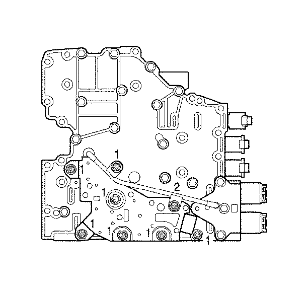
- Remove the six bolts (1) and one bolt (2), holding the reverse signal tube and pressure switch assembly to the main valve body.
- Remove reverse signal tube (2) from main valve body (3).
- Remove pressure switch assembly (1) from main valve body (3).
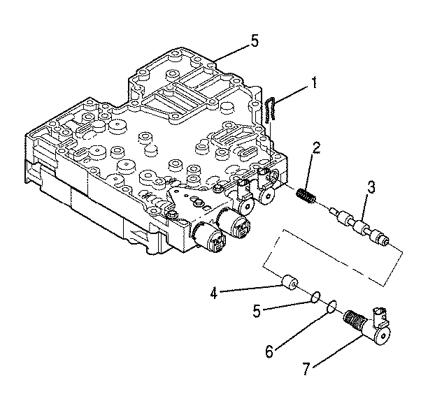
- Remove F trim solenoid retainer (1).
- Remove F trim solenoid (7), sleeve (4), valve (3), and spring (2).
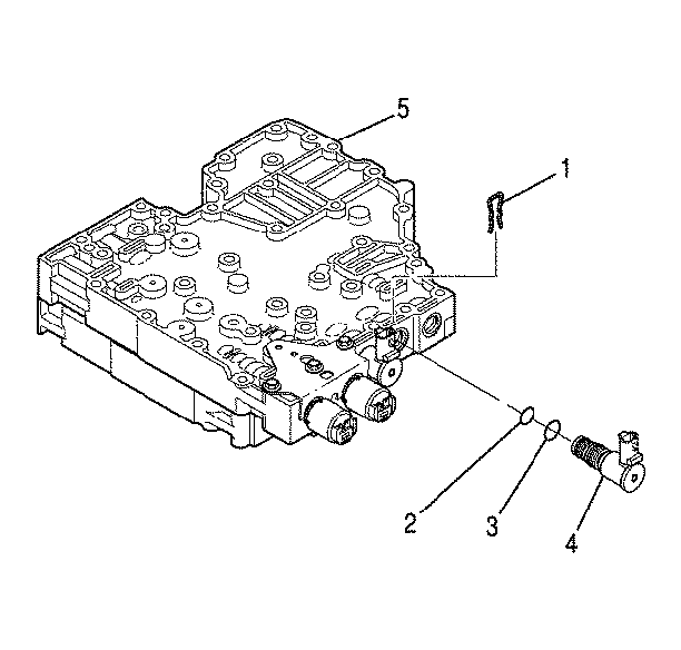
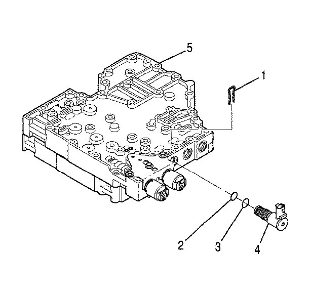
- Remove D ON/OFF shift solenoid retainer (1).
- Remove D ON/OFF shift solenoid (4).
- Remove O-rings (2,3) from D ON/OFF shift solenoid (4).
- Remove E ON/OFF shift solenoid retainer (1).
- Remove E ON/OFF shift solenoid (4).
- Remove O-rings (2,3) from E ON/OFF shift solenoid (4).
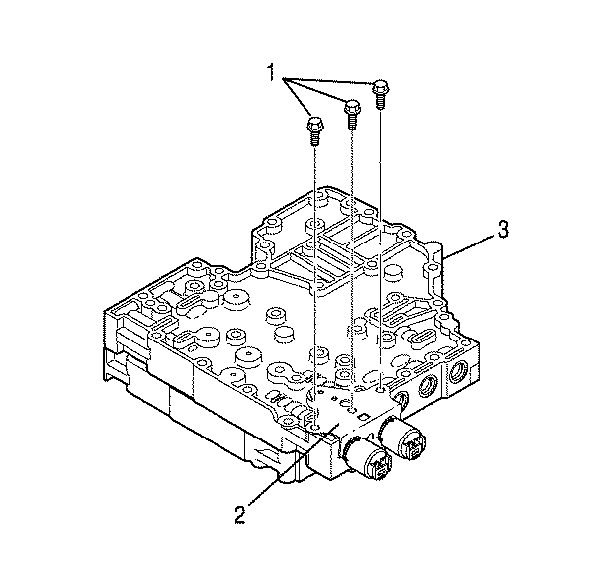
- Remove three bolts (1) holding A/B solenoid bracket (2) to main valve body (3).
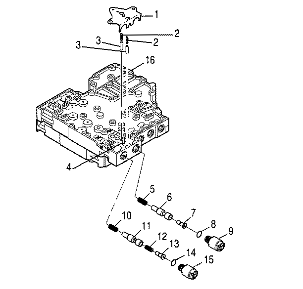
- Remove A/B solenoid bracket (1), two accumulator springs (2), and two accumulator plugs (3).
- Remove A trim solenoid (15), valve (13), spring (12) if present, valve (11), and spring (10).
- Remove O-ring (14) from A trim solenoid (15).
- Remove B trim solenoid (9), valve (7), valve (6), and spring (5).
- Remove O-ring (8) from B trim solenoid (9).
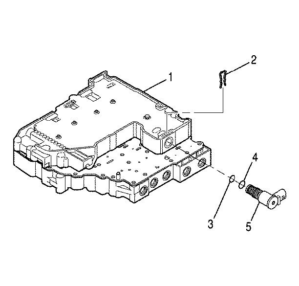
- Position the control valve assembly on the work table so that shift valve body (1) is facing up.
- Remove C ON/OFF shift solenoid retainer (2).
- Remove C ON/OFF shift solenoid (5).
- Remove O-rings (3,4) from C ON/OFF shift solenoid (5).
- Position the control valve assembly on the work table so that the main valve body is facing up.
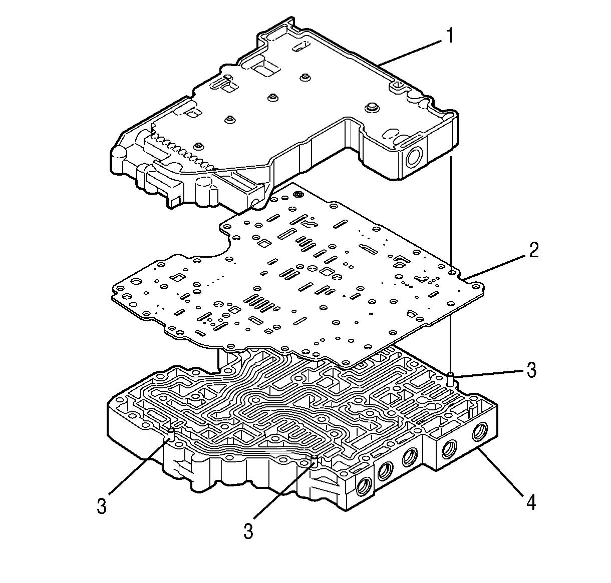
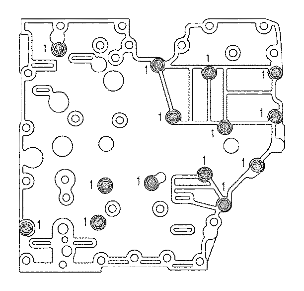
- Remove fourteen bolts (1) holding the shift valve body to the main valve body.
- Position the control valve assembly on the work table so that the assembly is on edge (sideways).
- Reinstall four bolts (1) so that the bolts are partially threaded into the shift valve body and protrude from the main valve body.
- Gently tap on the bolts until the assembly separates.
- Position the control valve assembly on the work table so that shift valve body (1) is facing up.
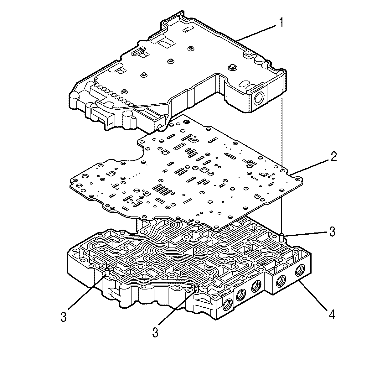
- Remove shift valve body assembly (1) and separator plate (2).
Notice: Refer to Transmission Control Valve Body Overhaul Notice in the Preface section.
Notice: Do not damage the solenoid(s) when turning over the control valve assembly.
Disassembly of Shift Valve Body
Tools Required
| • | J 33163 Valve Tray Set |
| • | J 43773 Valve Spring Compressor |
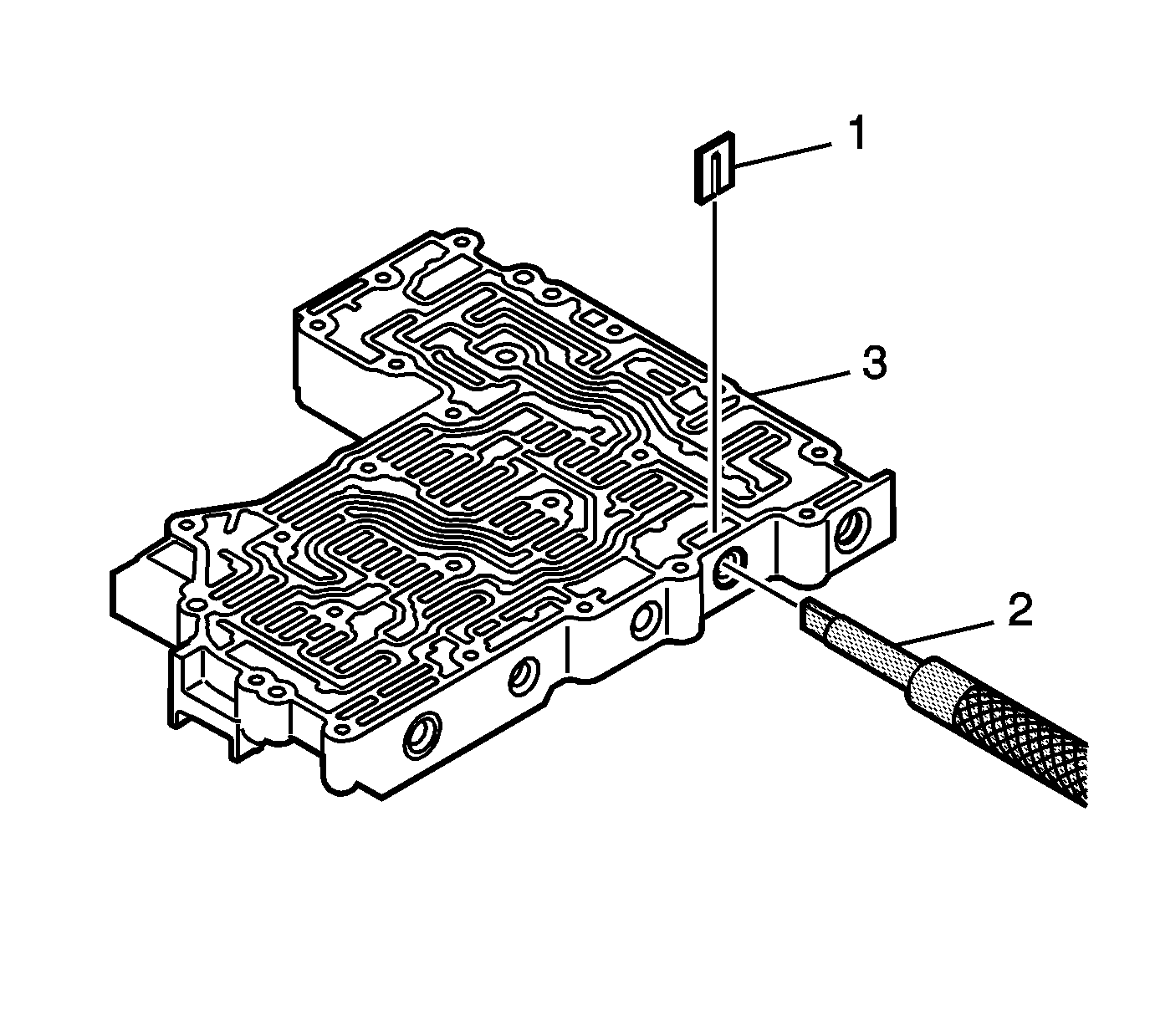
- Using tool J 43773 (2) , compress the C shift valve spring until retaining clip (1) is loose. Remove retaining clip (1).
- Remove spring (2) and C shift valve (1).
- Using tool J 43773 (2), compress the E shift valve spring until retaining clip (1) is loose. Remove retaining clip (1).
- Remove plug (3), spring (2), and E shift valve (1).
- Using tool J 43773 (2), compress the D shift valve spring until retaining clip (1) is loose. Remove retaining clip (1).
- 707170
- Using tool J 43773 (2), compress the control main valve spring until retaining clip (1) is loose. Remove retaining clip (1).
- Remove spring (2) and control main valve (1).
- Remove solenoid screen (1).
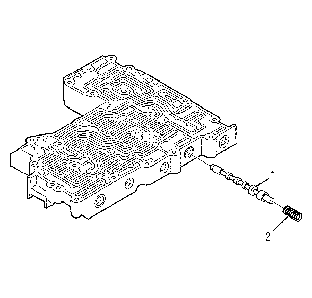
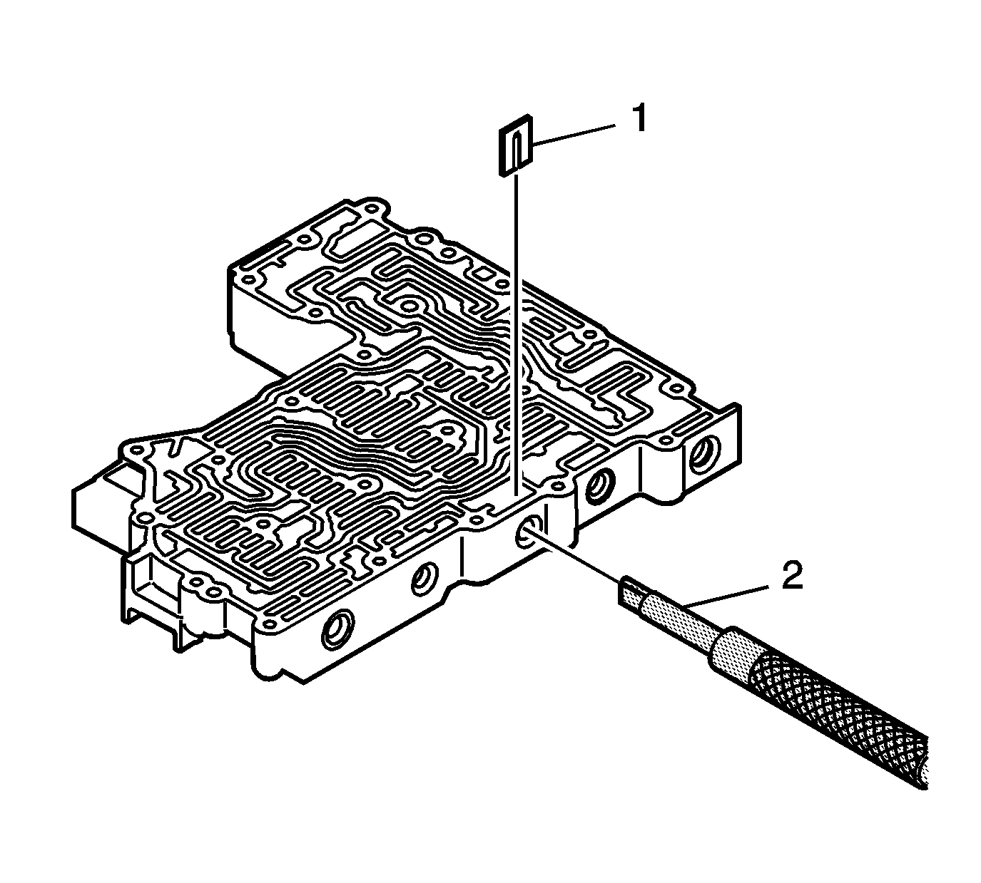

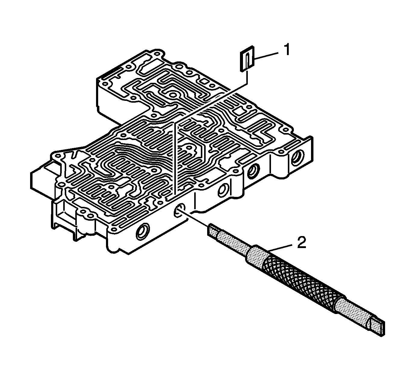
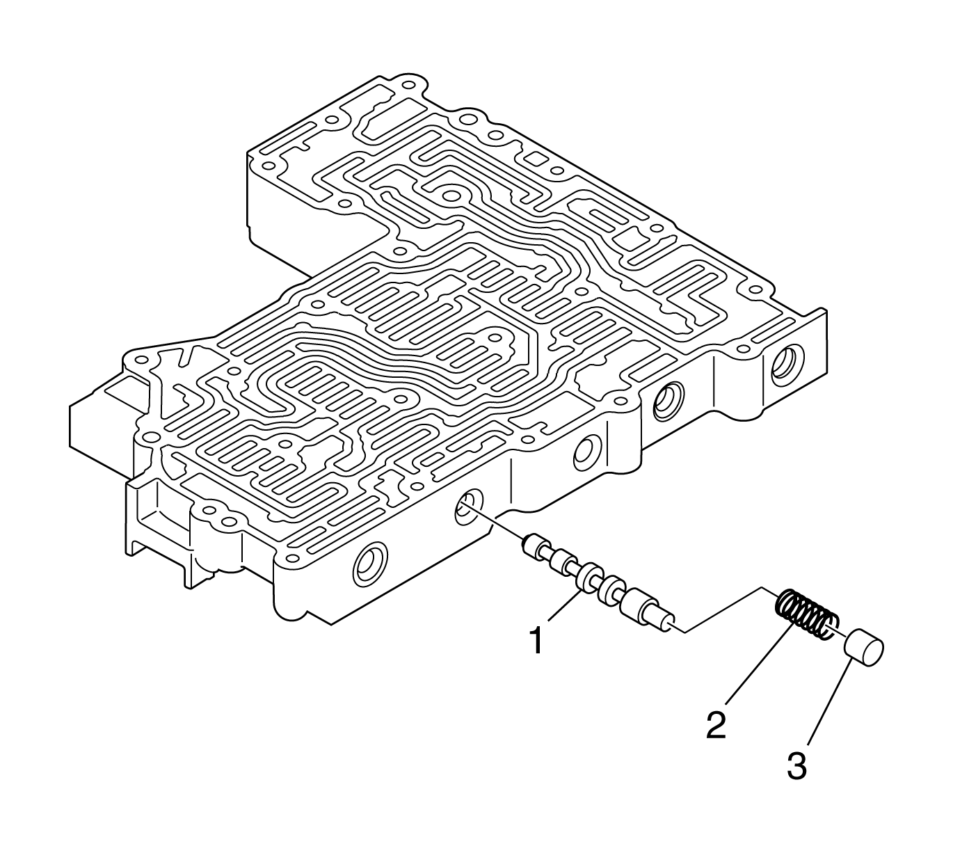
Remove plug (3), spring (2), and D shift valve (1).
Disassembly of Main Valve Body
Tools Required
| • | J 33163 Valve Tray Set |
| • | J 43773 Valve Spring Compressor |
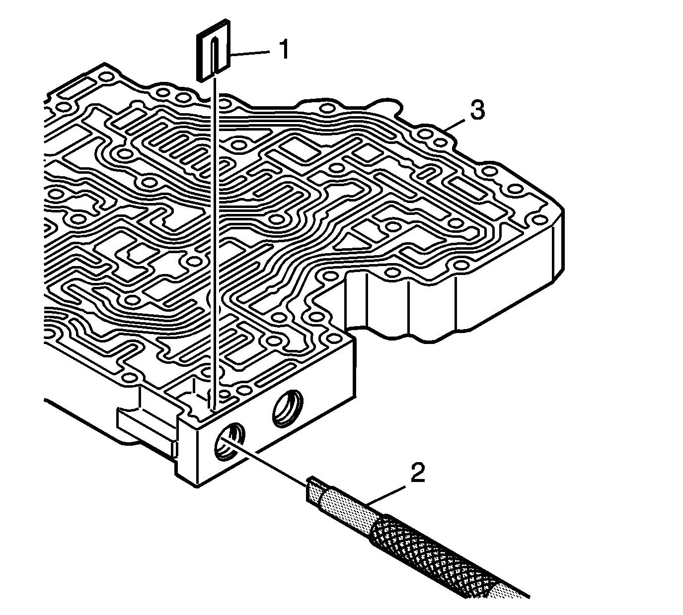
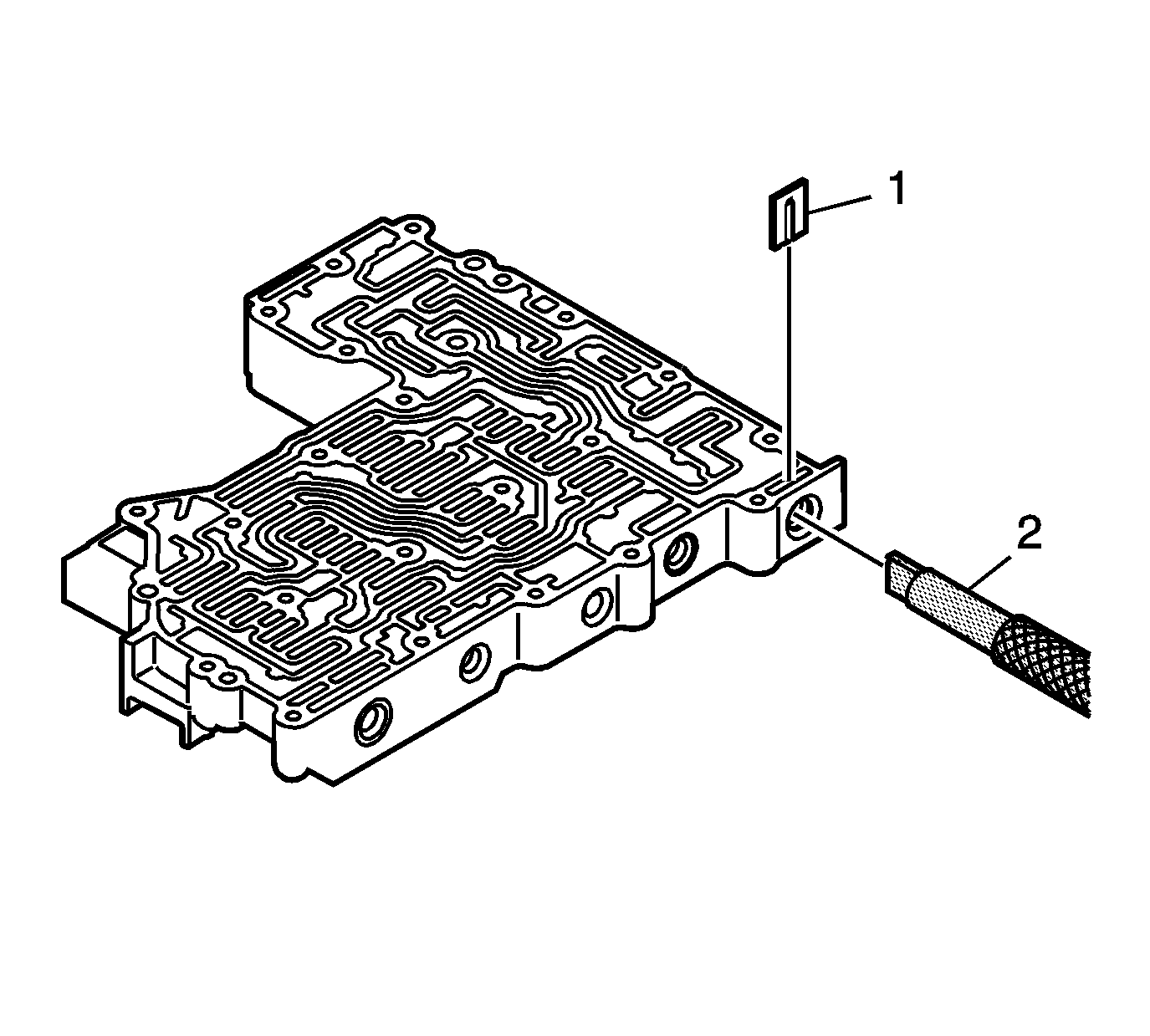
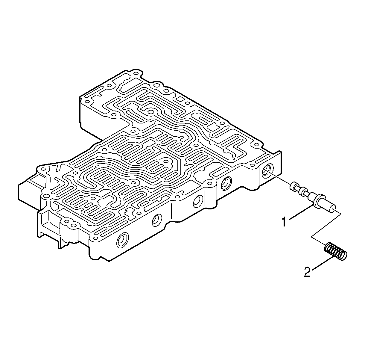
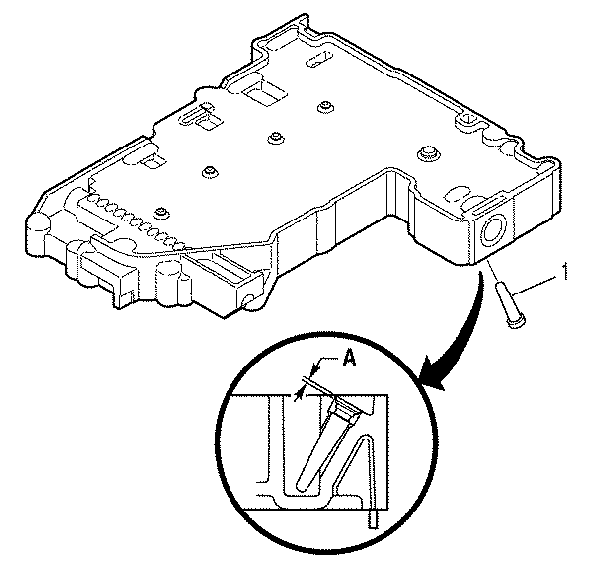
- Using tool J 43773 (2), compress the control relief spring until retaining clip (1) is loose. Remove retaining clip (1).
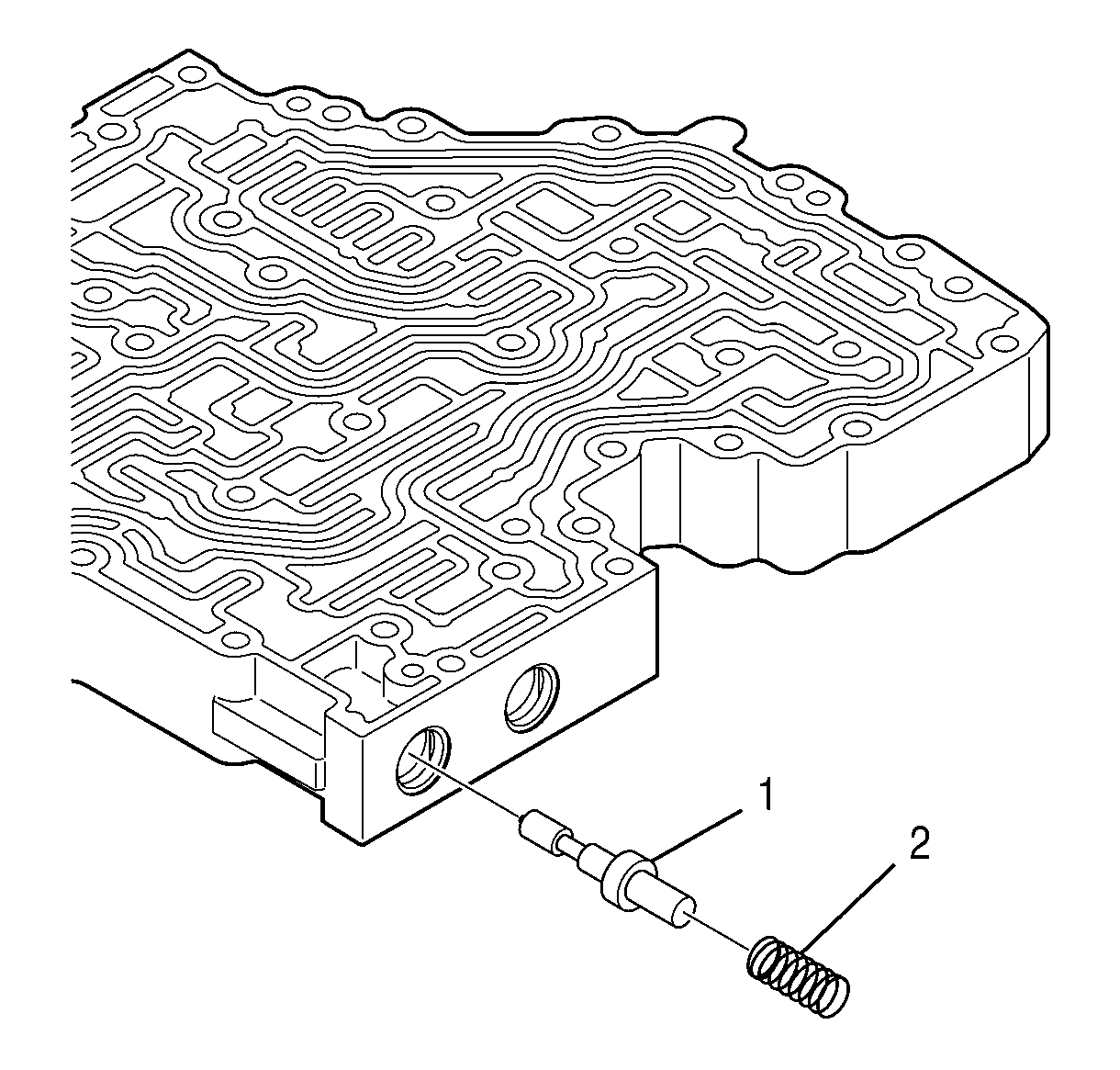
- Remove spring (2) and control relief valve (1).
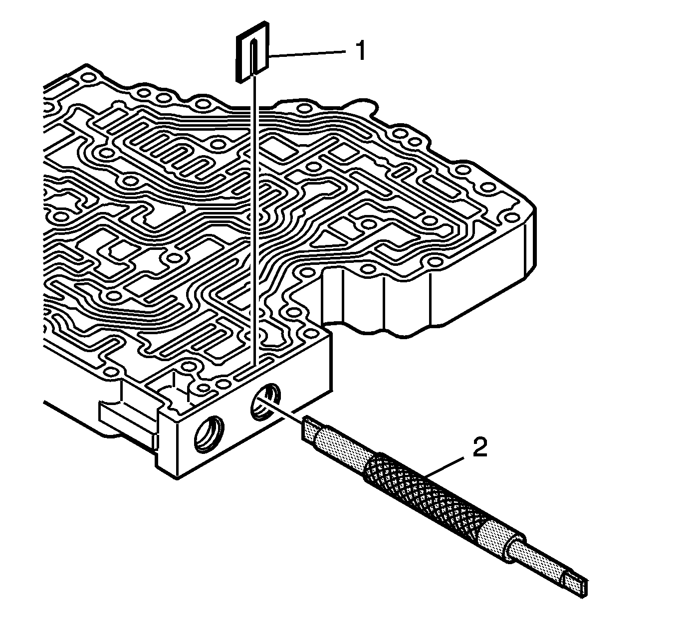
- Using tool J 43773 , compress the exhaust backfill spring until retaining clip (1) is loose. Remove retaining clip (1).
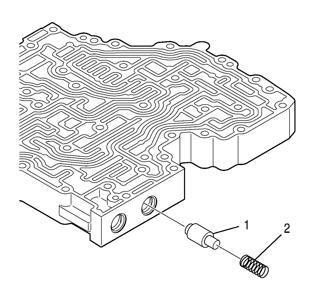
- Remove spring (2) and backfill exhaust valve (1).
