Info - Auxiliary Fuel Tank Removal Procedure

| Subject: | Auxiliary Fuel Tank Removal Procedure |
| Models: | 2001-2002 Chevrolet and GMC C/K 3600 Chassis Cab Models |
| with Auxiliary Fuel Tank |
The purpose of this bulletin is to provide a procedure to convert production C/K 3600 Chassis Cab trucks with dual fuel tanks to a single fuel tank. Follow the procedure listed below.
Any deviation from this procedure will nullify the vehicle warranty. An authorized GM dealer must complete this procedure. This is a customer paid conversion and the dealership must not charge the General Motors warranty system with the costs associated with completing this procedure.
- Disconnect the fuel feed and vapor pipe assembly by completing the following steps:
- Remove the six bolts (3) that attach the auxiliary fuel tank protective metal shield (2) to the frame (1). Remove the shield.
- Remove the two auxiliary fuel tank straps by completing the following steps:
- Remove the fuel feed and vapor pipe assembly (1) by completing the following steps:
- Remove the balance-T and the hose connecting the balance-T to the main fuel tank by removing the two clamps. Refer to Figure 3.
- Connect the vent hose, which is part of the fuel filler hose assembly, to the main fuel tank vent pipe by securing the pipe using one clamp.
- Remove the electric balance module assembly by removing the two bolts from the bracket securing the module to the frame assembly.
- Disconnect the rear extension wire harness assembly from the main fuel tank.
- Disconnect the fuel tank ground wire from the frame assembly by loosening and removing the bolt securing the wire to the frame assembly.
- Remove the rear harness wire extension assembly by completing the following steps:
- Connect the replacement rear harness wire extension assembly to the engine harness and instrument panel wire assemblies. Refer to the Parts Information table below for the correct harness and usage.
- Secure the rear harness wire extension assembly to the frame assembly by completing the following steps:
- Connect the rear harness wire extension assembly to the main fuel tank assembly.
- Connect the rear harness wire extension assembly to the diesel fuel pump.
- Connect the rear harness wire extension assembly to the rear taillight wire harness.
- Connect the rear harness wire extension assembly electrical ground and the main fuel tank electrical ground to the frame assembly by tightening the bolt.
- Connect the diesel fuel pump electrical ground to the frame assembly by tightening the bolt to the frame assembly. Note the connection point to the frame is identical to the connection point reference in Step 15.
- Reprogram the ECM/PCM using the applicable fuel system and engine diagnostic calibration part numbers listed below. The fuel system calibration and the engine diagnostic calibration should be changed when the fuel tank configuration is changed.
- For gasoline engines ONLY, use the Tech 2 to trigger the ECM/PCM to run OBD II diagnosis in order to inspect for fuel system leaks. Make any necessary repairs if leaks are detected.
- Affix a fuel system modification notice label, P/N 15036254, to the inside of the glove box in order to document that the auxiliary fuel tank has been removed from this truck and the ECM/PCM has been reprogrammed, if applicable.
- The authorized GM dealership must contact the Techline Customer Support Center (TCSC) at 1-800-828-6860 to request the VCI number and provide the TCSC with the VIN and the required calibration of the vehicle being converted to production single fuel tank system.
- The TCSC will update General Motors' database with the new calibration number of the vehicle being converted for future reference.
Figure 1
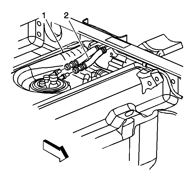
| 1.1. | Disconnect the fuel feed and fuel vapor hoses (2) from the auxiliary fuel tank (1). |
Figure 2
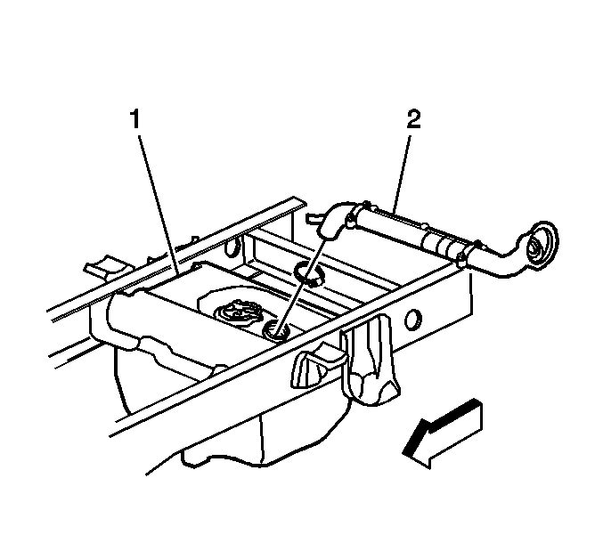
| 1.2. | Disconnect the fuel fill hose (2), which is part of the hose assembly, from the auxiliary fuel tank (1). |
| 1.3. | Disconnect the fuel vent hose, which is part of the fuel filler hose assembly, from the auxiliary fuel tank. |
Figure 3
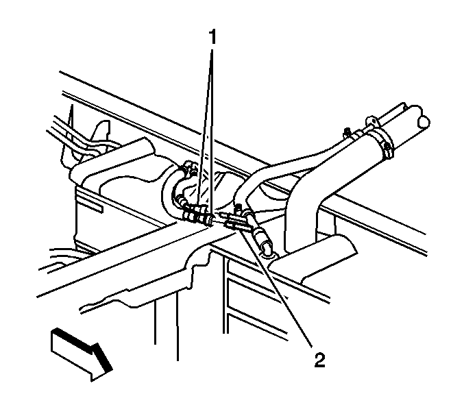
| 1.4. | Disconnect the fuel feed and vapor hose (1), which is part of the fuel feed and fuel vapor pipe assembly from the balance-T (2). |
Figure 4
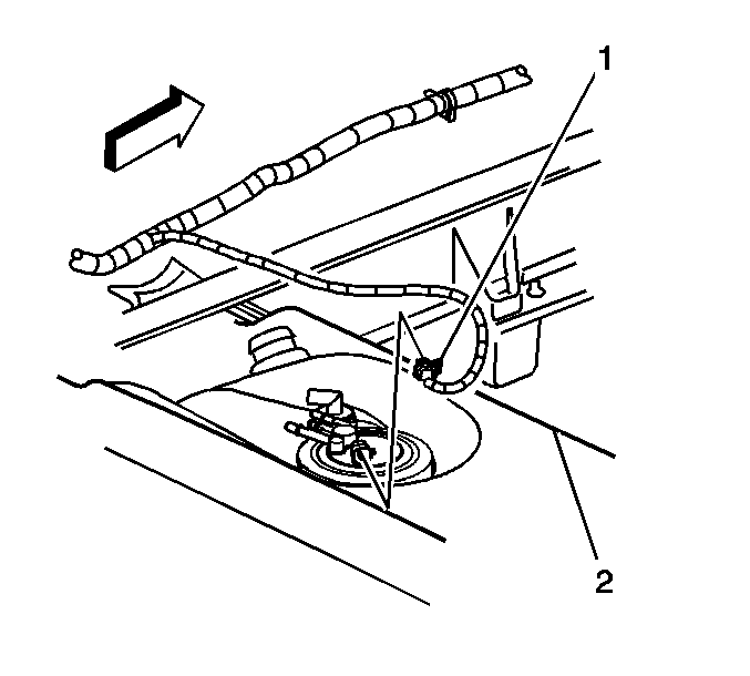
| 1.5. | Disconnect the rear extension wire harness assembly connector (1) from the auxiliary fuel tank (2). |
Figure 5
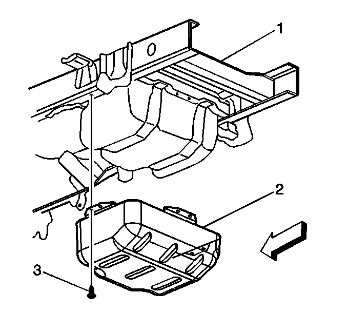
Figure 6
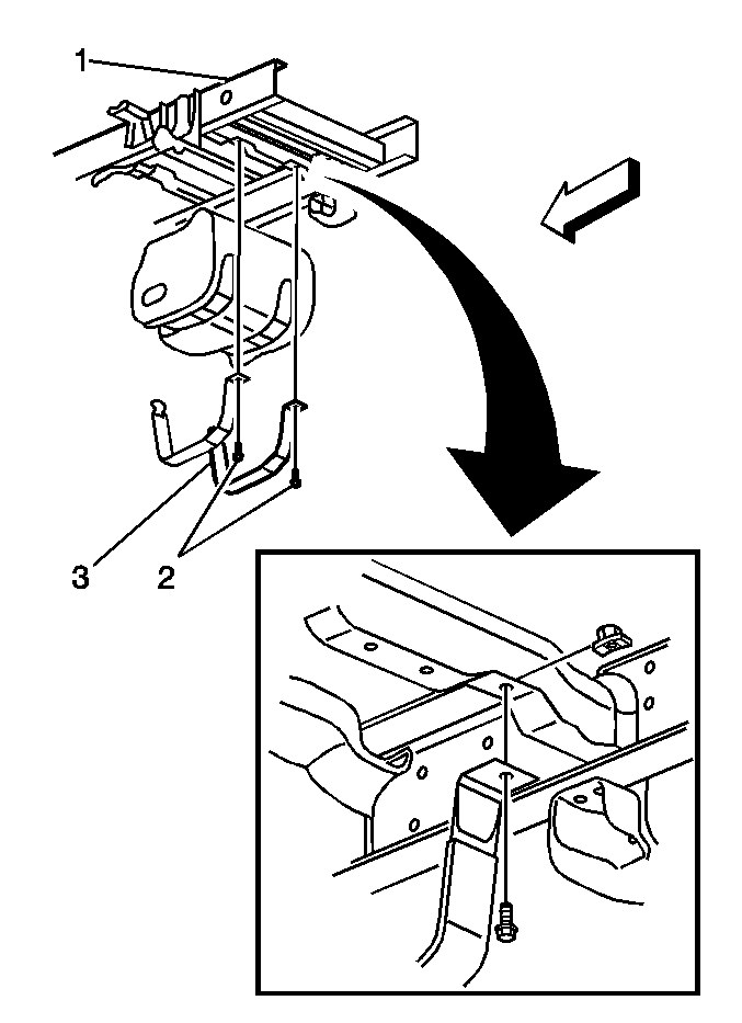
| 3.1. | Loosen and remove one bolt (2) per each strap (3). |
| 3.2. | Remove the two J-nuts from the frame assembly (1). |
Figure 7 (Gas)
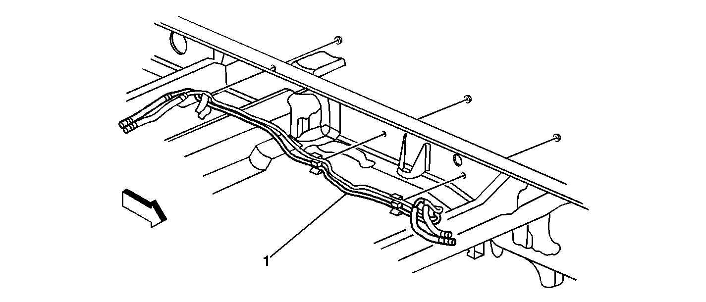
Figure 7 (Diesel)
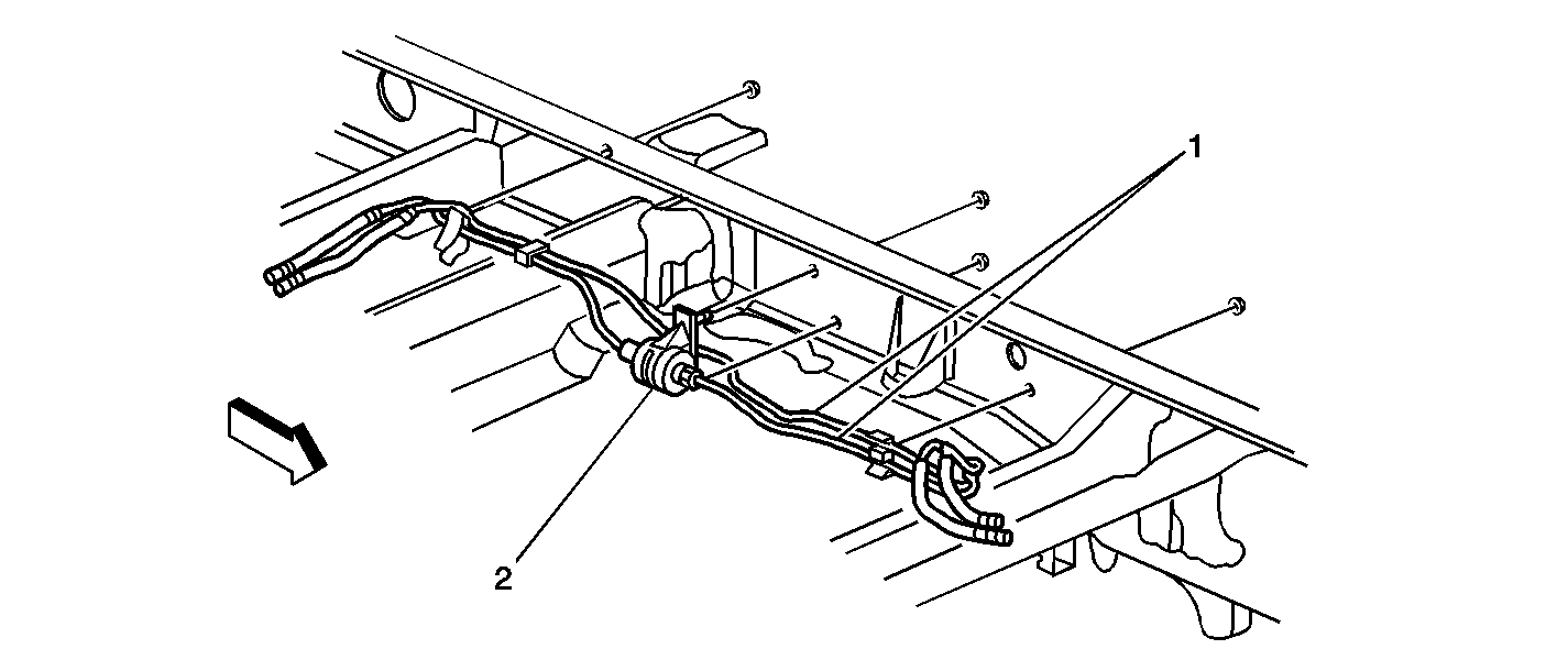
| 4.1. | On diesel models, loosen and remove the two nuts that secure the fuel pump clip (2) to the frame assembly. |
| 4.2. | Loosen and remove one nut per each retainer clip secured to the frame assembly. |
| 4.3. | Push the fuel feed and vapor pipe assemblies out of the retainer clips with your fingers. |
| 4.4. | Slide the fuel feed and vapor pipe assemblies out of the frame assembly and out of the truck. |
Figure 8
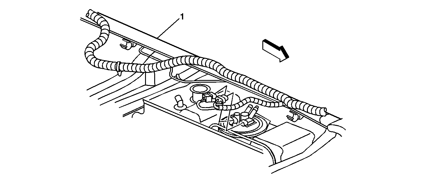
Figure 9
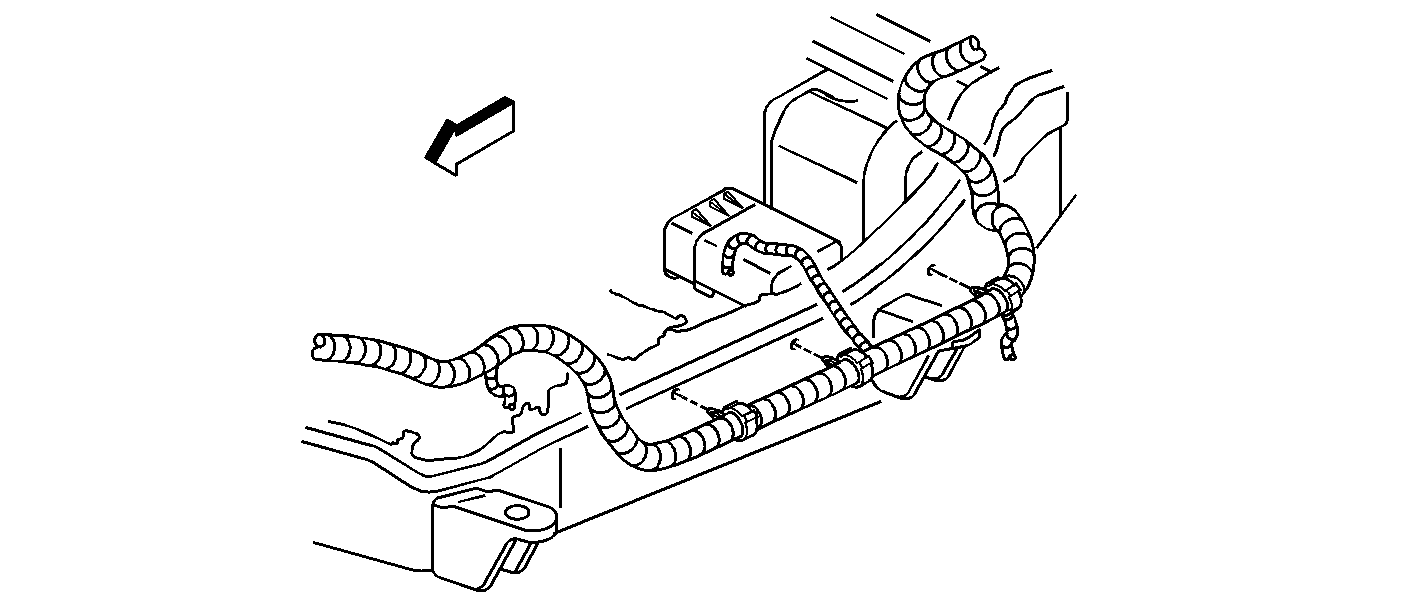
Important: For diesel engine equipped trucks, disconnect the fuel pump ground wire from the frame assembly at the same connection point as the fuel tank assembly.
| 10.1. | Disconnect the band ties. |
| 10.2. | Remove the rear harness wire extension assembly from the retainer clips by pushing the harness out of the retainer clips. |
| 10.3. | Disconnect the rosebud clip holding the rear harness wire extension assembly from the frame assembly. |
Figure 10
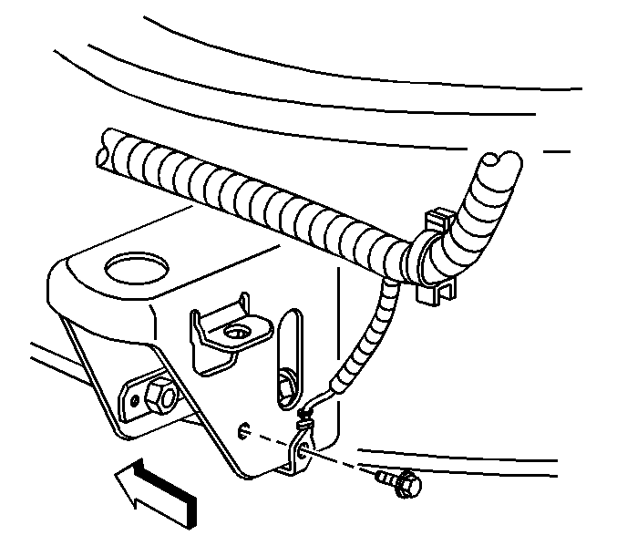
| 10.4. | Loosen and remove one bolt from the clip securing the rear harness wire extension assembly to the frame assembly. |
Figure 11
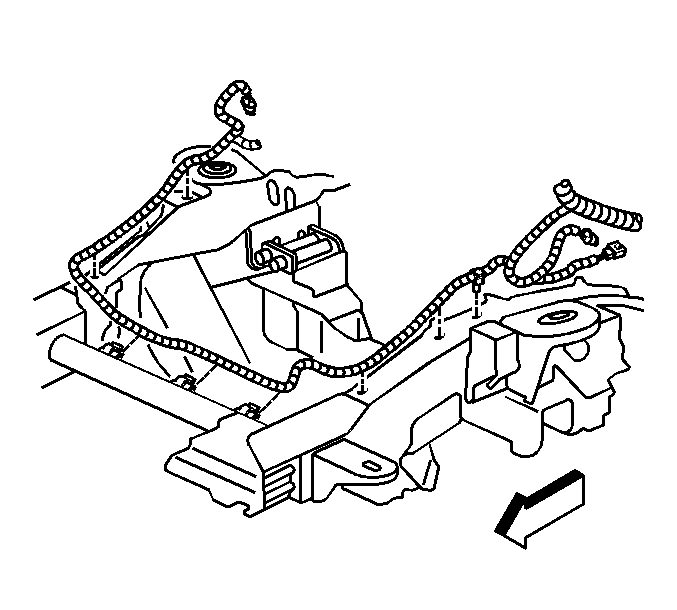
| 10.5. | Disconnect the rear harness wire extension assembly at the connections to the engine harness and instrument panel wire assemblies. |
Figure 12
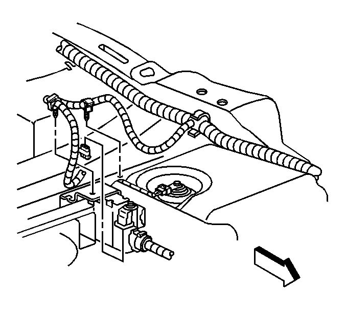
| 10.6. | Disconnect the rear harness wire extension assembly at the location of the enhanced evaporative emission connection. |
| 10.7. | For gasoline engines only, place the cap on the engine harness single pin connector. The cap consists of the following components: |
| • | A connector, P/N 12065172 |
| • | TPA, P/N 12065249 |
| • | Cavity plug, P/N 12010300 |
Figure 13
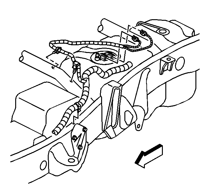
| 12.1. | Secure the clip, which is part of the rear harness wire extension assembly, to the frame assembly by tightening the bolt. |
| 12.2. | Secure the rosebud clips, which hold the rear harness wire extension assembly, to the frame assembly. |
| 12.3. | Push the rear harness wire extension into the retainer clips. |
| 12.4. | Secure the band ties, which hold the rear harness wire extension assembly, to the frame assembly. |
Important: This step should be completed for diesel engine equipped trucks. This step is not required for gas engine equipped trucks.
Important: This step should be completed for diesel engine equipped trucks. This step is not required for the gas engine equipped trucks.
Calibration Information
2001 Fuel Calibrations | |||
|---|---|---|---|
Calibration P/N | Fuel Tank | Engine | Emissions |
15063381 | Single | LB7 | All |
15063382 | Dual | LB7 | All |
16264588 | Single | LQ4/L18 | All |
16264637 | Dual | LQ4/L18 | Fed/Leaded Export |
16264638 | Dual | LQ4/L18 | California |
2002 Fuel Calibrations | |||
|---|---|---|---|
Calibration P/N | Fuel Tank | Engine | Emissions |
15085502 | Single | LB7 | All |
15085503 | Dual | LB7 | All |
16264588 | Single | LQ4 | All |
16264637 | Dual | LQ4 | Fed/Leaded Export |
16264638 | Dual | LQ4 | California |
16264617 | Single | L18 | All |
16264615 | Dual | L18 | Fed/Leaded Export |
16264616 | Dual | L18 | California |
2001 Engine Diagnostic Calibrations | |||
|---|---|---|---|
Calibration P/N | Fuel Tank | Engine | Emissions |
09358106 | Dual | LQ4/MW3 | Fed |
09358108 | Dual | LQ4/MW3 | Leaded Export |
09362549 | Single | LQ4/MW3 | California |
09362552 | Dual | LQ4/MW3 | California |
16264011 | Single | LQ4/MW3 | Fed |
16264012 | Single | LQ4/MW3 | Leaded Export |
09362445 | Dual | LQ4/MT1 | Fed |
09362446 | Dual | LQ4/MT1 | Leaded Export |
09362541 | Single | LQ4/MT1 | California |
09362551 | Dual | LQ4/MT1 | California |
16264001 | Single | LQ4/MT1 | Fed |
16264007 | Single | LQ4/MT1 | Leaded Export |
09362441 | Single | L18/M74 | California |
09362443 | Dual | L18/M74 | California |
09362444 | Dual | L18/M74 | Fed |
16264018 | Single | L18/M74 | Fed |
09362553 | Single | L18/ML6 | California |
09362555 | Dual | L18/ML6 | California |
09362578 | Dual | L18/ML6 | Fed |
16264019 | Single | L18/ML6 | Fed |
2002 Engine Diagnostic Calibrations | |||
|---|---|---|---|
Calibration P/N | Fuel Tank | Engine | Emissions |
09358917 | Dual | LQ4/MW3 | Fed/Fleet |
09358920 | Dual | LQ4/MW3 | California |
09362638 | Single | LQ4/MW3 | California |
09362640 | Single | LQ4/MW3 | Fed/Fleet |
09358918 | Dual | LQ4/MT1 | Fed/Fleet |
09358919 | Dual | LQ4/MT1 | California |
09362622 | Single | LQ4/MT1 | Fed/Fleet |
09362624 | Single | LQ4/MT1 | California |
09358098 | Single | L18/ML6 | Fed/Fleet |
09362569 | Dual | L18/ML6 | Fed/Fleet |
09358982 | Single | L18/M74 | Fed/Fleet |
09358985 | Dual | L18/M74 | Fed/Fleet |
09362566 | Single | L18/ML6 | California |
09362570 | Dual | L18/ML6 | California |
09358984 | Single | L18/M74 | California |
09358986 | Dual | L18/M74 | California |
The calibrations listed are electronic calibrations and are NOT available from GMSPO. Calibrations are available from Techline on TIS 2000 data version 6 for 2001 or later.
Parts Information
Part Number | Description | Series/Options |
|---|---|---|
12172650 | Harness Asm - Chassis Wiring | 360, 364 w/ LQ4/L18 and NQZ, UY7, 5X7 w/o EVA/8S3 |
360, 364 w/ LQ4/L18 and NQZ, UY7, 5Y0 w/o EVA/5X7/8S3 | ||
360, 364 w/ LQ4/L18 and NQZ, UY7, 8S3 w/o EVA | ||
12172652 | Harness Asm - Chassis Wiring | 360, 364 w/ LQ4/L18 and EVA, NQZ, UY7, 5X7 w/o 8S3 |
360, 364 w/ LQ4/L18 and EVA, NQZ, UY7, 5Y0 w/o 5X7/8S3 | ||
360, 364 w/ LQ4/L18 and EVA, NQZ, UY7, 8S3 | ||
15057563 | Harness Asm - Chassis Wiring | 360 w/ LB7, NQZ, UY7 |
15057564 | Harness Asm - Chassis Wiring | 360 w/ LB7, NQZ, UY7 |
15057565 | Harness Asm - Chassis Wiring | 364 w/ LB7, NQZ, UY7 |
15057566 | Harness Asm - Chassis Wiring | 364 w/ LB7, NQZ, UY7 |
15058858 | Harness Asm - Chassis Wiring | 360 w/ LQ4/L18 and EVA, NQZ, UY7 w/o 5X7/5Y0/8S3 |
15058859 | Harness Asm - Chassis Wiring | 360 w/ LQ4/L18 and EVA, NQZ, UY7 w/o 5X7/5Y0/8S3 |
15058860 | Harness Asm - Chassis Wiring | 364 w/ LQ4/L18 and EVA, NQZ, UY7 w/o 5X7/5Y0/8S3 |
15058861 | Harness Asm - Chassis Wiring | 364 w/ LQ4/L18 and EVA, NQZ, UY7 w/o 5X7/5Y0/8S3 |
15036254 | Fuel System Modification Label | |
12065172 | Connector | |
12065249 | TPA | |
12010300 | Cavity Plug |
Parts are currently available from GMSPO.
RPO Definitions
RPO Code | Description |
|---|---|
LB7 | Engine, 6.6L Diesel |
LQ4 | Engine, 6.0L Gas |
L18 | Engine, 8.1L Gas |
NQZ | Fuel Tank, Aux. Rear Mount - Delete |
UY7 | Wiring Harness, Truck Trailer HD |
5X7 | Provisions, Wrecker Emergency Lamp |
5Y0 | Wiring Provision, Body Builder Emergency Lamp |
8S3 | Alarm, Back-Up |
EVA | Evap Emission Requirement |
