Removal Procedure
Notice: In order to prevent damage to the crankshaft position (CKP) sensor reluctor wheel/ring, care must be used when removing or installing this component.
- Raise and suitably support the vehicle. Refer to Lifting and Jacking the Vehicle in General Information.
- Remove the fuel line bracket nut (2).
- Remove the fuel line bracket from the bellhousing stud.
- Lower the vehicle.
- Remove the driver side rear ignition coil bolts.
- Reposition the ignition coil.
- Disconnect the crankshaft position (CKP) sensor electrical connector.
- Use penetrating oil and allow the oil to soak around the CKP sensor prior to removing the sensor.
- Remove the CKP sensor bolt.
- Twist the CKP sensor back and forth.
- Pull the sensor straight up in order to remove the CKP sensor.
- Inspect the CKP sensor for wear.
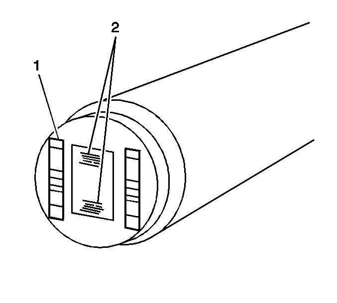
- Normal CKP sensor wear will be shown on the wear strips (1) and no wear will be shown on the sensor sensing element (2).
- Excessive or abnormal sensor wear will be shown on the sensing element (2).
- If excessive/abnormal wear is present, replace the sensor.
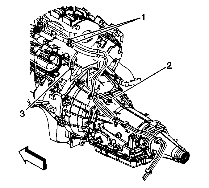
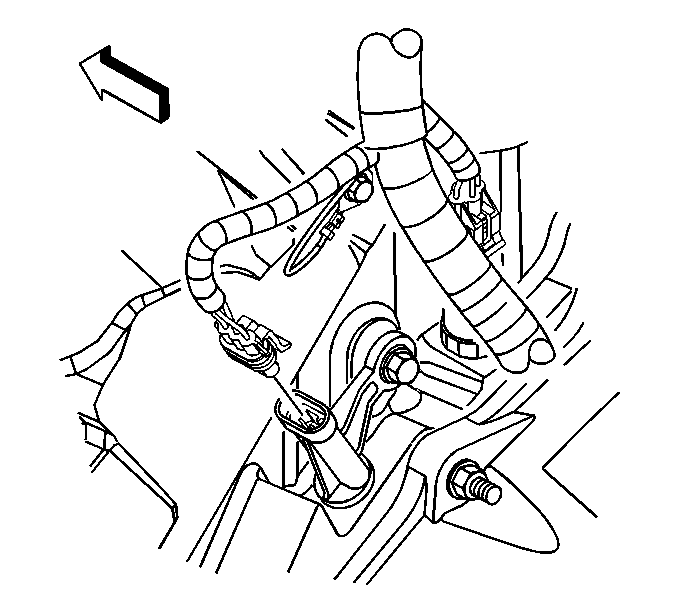
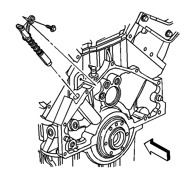
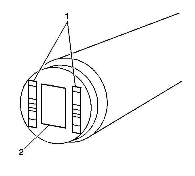
Important: The CKP sensor is designed to contact the reluctor wheel of the crankshaft. Wear may be noticeable on the end of the sensor.
Installation Procedure
- If reusing the old sensor, Inspect both O-rings for cuts, cracks, tears or damage, replace the O-rings as needed.
- Lubricate the CKP sensor O-rings with clean engine oil.
- Install the CKP sensor.
- If reusing the old sensor, apply thread adhesive GM P/N 12345493 (Canadian P/N 10953488) or equivalent to the threads.
- Install the CKP sensor bolt.
- Connect the CKP sensor electrical connector.
- Position the ignition coil to the rocker cover.
- Install the driver side rear ignition coil bolts.
- Raise the vehicle
- Install the fuel line bracket to the bellhousing stud.
- Install the fuel line bracket nut (2).
- Lower the vehicle.
- Perform the CKP system variation learn procedure. Refer to Crankshaft Position System Variation Learn .

Important: Ensure that the CKP sensor is fully seated against the crankshaft reluctor ring. The upper flange on the sensor MAY NOT seat against the engine block.
Important: The CKP sensor bolt has adhesive applied to the threads. The adhesive may have come off during removal of the bolt. Ensure that the bolt hole is clean of any debris before installing the reinstalling bolt.
Notice: Use the correct fastener in the correct location. Replacement fasteners must be the correct part number for that application. Fasteners requiring replacement or fasteners requiring the use of thread locking compound or sealant are identified in the service procedure. Do not use paints, lubricants, or corrosion inhibitors on fasteners or fastener joint surfaces unless specified. These coatings affect fastener torque and joint clamping force and may damage the fastener. Use the correct tightening sequence and specifications when installing fasteners in order to avoid damage to parts and systems.
Tighten
Tighten the bolt to 12 N·m (106 lb in).

Tighten
Tighten the bolts to 12 N·m (106 lb in).

Tighten
Tighten the nut to 10 N·m (89 lb in).
