The New Venture Gear (NVG) 261, RPO NP2 transfer case is a two-speed, part-time with "mode shift-on-the-fly" capability. It has a chain driven front output shaft and an epicyclical low range planetary arrangement. The NVG 261 transfer case features a four position shift lever control located in the vehicle floor plan. As required, the operator can select 4HI position from 2HI "on-the-fly," as described in the owners manual. A dash 4WD lamp continues flashing during shifting, until all criteria have been met and the new mode/range position has been reached. Once the new mode/range position is fully engaged and the front axle disconnect locks in, the dash light 4WD indicator lamp remains ON constantly. Range shifting functions similarly, although it should be limited to speeds 5 km/h (3 mph) or less.
The four manual mode, or range gear positions, of the NVG 261 transfer case are:
| • | 2HI - 2 wheel drive high range |
| • | 4HI - 4 wheel drive high range, part-time |
| • | 4LO - 4 wheel drive low range, 2.72:1 gear ratio reduction |
| • | N - Neutral, 4 wheel |
When the ignition switch is placed in the run position and the 4WD shift lever is in the 4WD position, the transfer case switch closes, supplying a ground to the axle actuator control circuit. With the ground applied, the logic of the front axle actuator actuates a DC motor to engage the front axle and supply voltage to the axle switch signal circuit. The axle switch signal circuit notifies the powertrain control module (PCM) and the Anti-Lock Brake System that the vehicle is in the 4WD mode. The 4WD indicator is commanded on via a Class 2 serial data signal from the PCM. When the 4WD shift lever is in the 4WD low range position, the transfer case switch closes and supplies a ground on the 4WD low signal circuit. This informs the PCM that the vehicle transfer case is in low range. When the vehicle is in low range, the PCM changes the shift pattern of the automatic transmission.
During normal driving situations, the transfer case can operate in the 2WD mode. The driver may choose to select any of the mode/range gear positions while driving the vehicle. However, the transfer case should not be shifted into or out of 4LO unless the following criteria have been met:
| • | The automatic transmission is in neutral or the clutch pedal is depressed. |
| • | The vehicle speed is less than 5 km/h (3 mph). |
This transfer case also has a neutral position. A shift to the neutral position allows the vehicle to be towed without rotating the transmission output shaft. In the neutral position, the rear propeller shaft rotates the transfer case rear output shaft, in turn rotating the oil pump, providing constant lubrication during towing. Note, this neutral position is a 4WD neutral, meaning the front and rear outputs of the transfer case are engaged as though in 4HI. With a disconnecting front axle, there is no power flow to the front wheels, allowing towing with the front wheels off the ground or flat towing without driveline binding. Again, the transfer case should not be shifted into or out of neutral unless the following criteria have been met:
| • | The automatic transmission is in neutral or the clutch pedal is depressed. |
| • | The vehicle speed is less than 5 km/h (3 mph). |
The NVG 261 transfer case is available in 5 variations, depending on the engine and transmission configurations. The variations allow the transfer case to handle different torque loads. When servicing the transfer case it is important to understand which variation is being serviced because of the difference in parts.
Model | Transmission | Input Gear | Output Shaft | Chain Size | Hi/Low Planetary | Application |
|---|---|---|---|---|---|---|
Light Duty (LD) | M30 - 4L60E | 27T Spline | 32T Spline | 3/8 X 1.25 in | 4 Pinion | K1 |
Light Duty (LD) | MG5 - NV 3500 | 32T Spline | 32T Spline | 3/8 X 1.25 in | 4 Pinion | K1 |
Heavy Duty 1 (HD1) | MT1 - 4L80E MW3 - NV 4500 | 32T Spline | 32T Spline | 3/8 X 1.5 in | 6 Pinion | K2 Non Heavy Duty |
Heavy Duty 2 (HD2) | MT1 - 4L80E MW3 - NV 4500 | 32T Spline | 32T Spline | 7/16 X 1.5 in | 6 Pinion | K2 Heavy Duty |
Super Heavy Duty (SHD) | ML6 - ZF S6-650 M74 - Allison | 29T Spline | 31T Spline | 7/16 X 1.5 in | 6 Pinion | K3 |
The SHD model shares many of the same components, but the increased torque capacity of the SHD requires a double row input bearing and larger diameter rear output shaft, rear output shaft bearing higher capacity, larger rear seal and case halves machined differently.
The NVG 261 has some internal changes for this model year. The oil pump on the LD and HD variations is now the same as the SHD variation. Along with the oil pump change, the oil pump suction pipe and screen were also changed. The NVG 261 now uses a different rear output shaft. The pilot bearing and cup plug in the input gear has been changed to a cup style bearing.
2WD Mode Power Flow

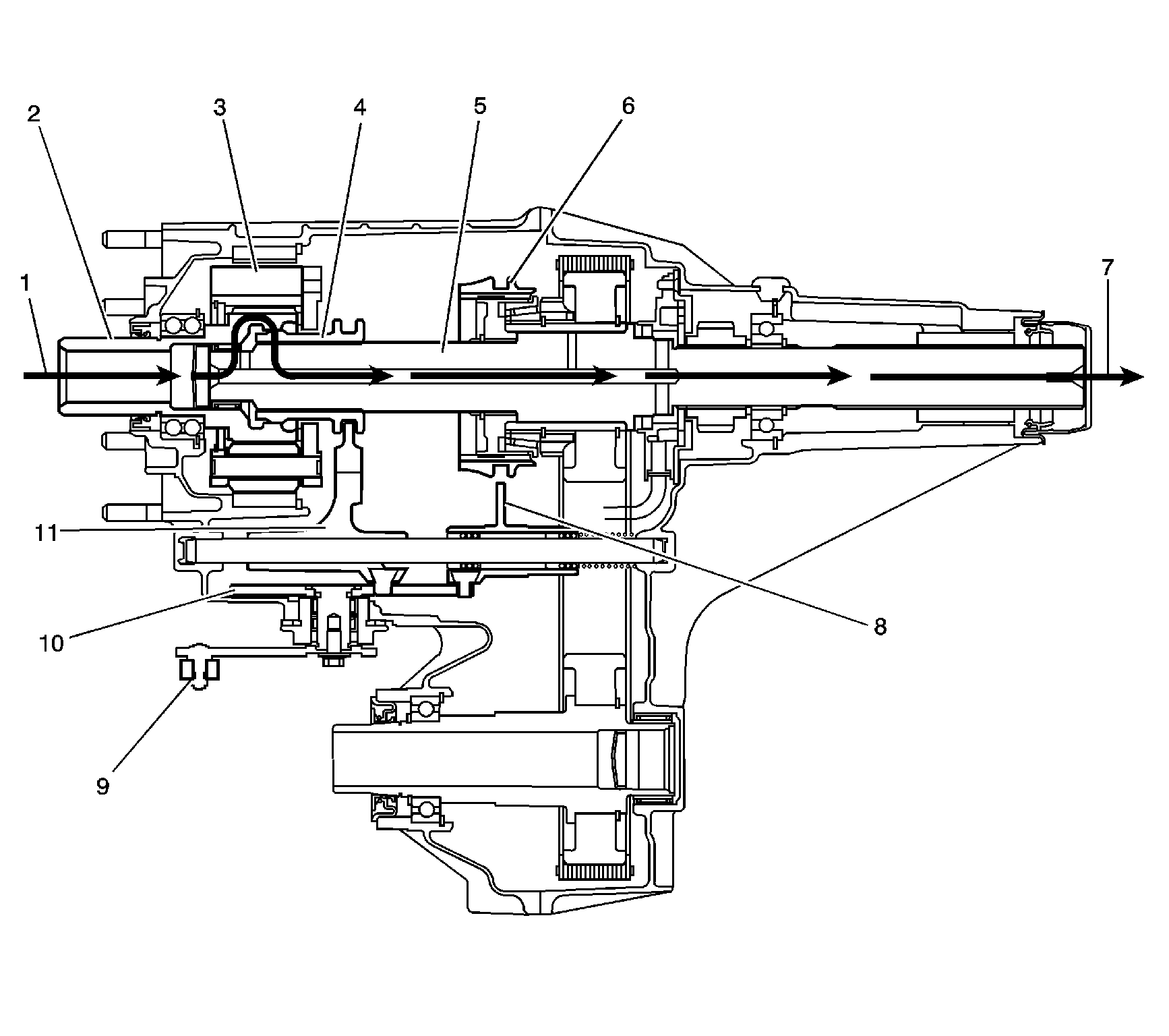
The transfer case is shifted by a remote mounted shift lever, which is connected by linkage to the shift lever (9) on the shift detent lever shaft. The shift detent lever shaft rotates the cam shaped shift detent lever (10) and moves the high/low range shift fork (11) or the 2/4 wheel drive mode shift fork (8). Depending on the selected mode or range, the shift forks move either the high/low range sleeve (4) for the high/low range planetary assembly (3) or the synchronizer sleeve (6) for the 2/4 wheel drive mode. In the 2WD mode, the engine power from the transmission (1) is delivered to the input shaft (2). The engagement teeth on the inside of the input shaft (2) are engaged to the outer teeth on the high/low range sleeve (4). The high/low range sleeve (4) is slipped splined to the rear output shaft (5). The engine power flows from the high/low range sleeve (4) to the rear output shaft (5) and is delivered to the rear propeller shaft (7).
4HI Mode Power Flow

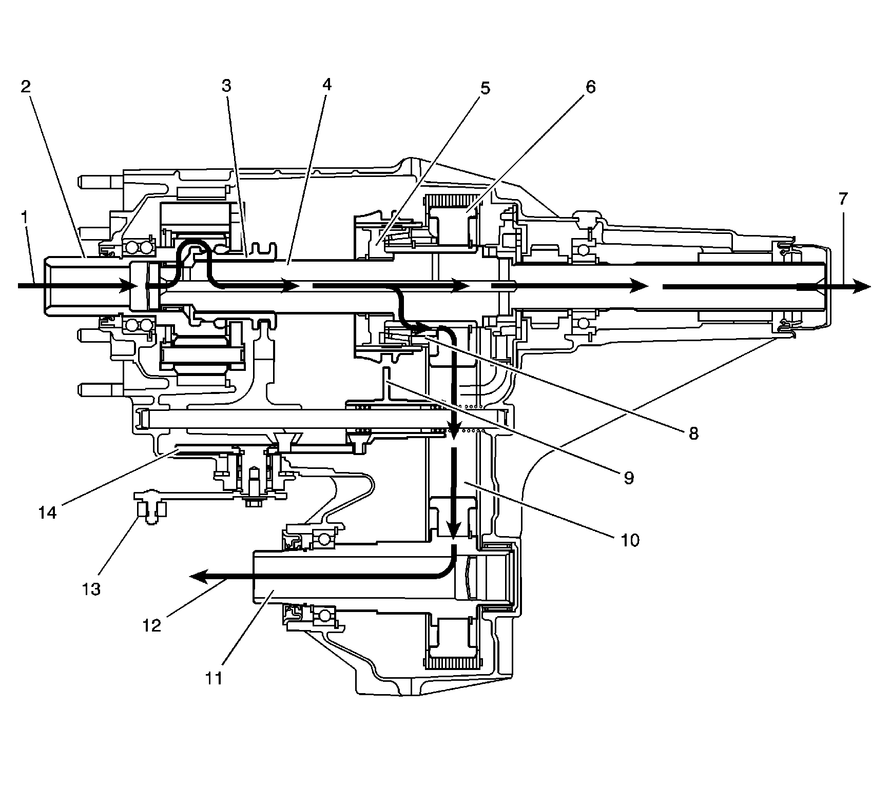
In the 4HI mode, the engine power from the transmission (1) is delivered to the input shaft (2). The engagement teeth on the inside of the input shaft (2) are engaged to the outer teeth on the high/low range sleeve (3). The high/low range sleeve (3) is slipped splined to the rear output shaft (4). During a shift mode from 2HI to 4HI the cam profile on the shift detent lever (14) pushes the 2/4 wheel drive mode shift fork (9) and the synchronizer sleeve. The sleeve, engaging the synchronizer (5) equalizes the front propeller shaft (12) and rear propeller shaft (7) speeds. Then the sleeve engages to the 2/4 wheel drive synchronizer gear (8), which is splined to the drive sprocket (6). The engine power flow for driving the front propeller shaft (12), now travels from the rear output shaft (4) to the synchronizer hub, which is splined to the rear output shaft (4). The power flows from the synchronizer hub to the sleeve and then to 2/4 wheel drive synchronizer gear (8). The power flow is transmitted by a chain (10) to the driven sprocket on the front output shaft (11) and to the front propeller shaft (12). The front and rear propeller shafts are being driven at equal RPMs, therefore giving a four wheel drive mode. This mode should only be used for extra traction. Using this mode on dry pavement causes tire scuffing when turning.
4LO Mode Power Flow

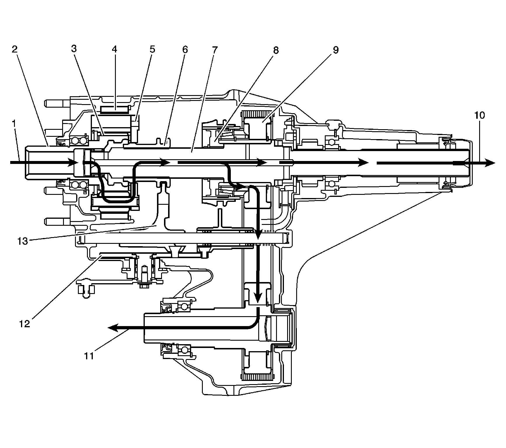
During range shift request to 4LO, a separate cam profile on the same shift detent lever (12) moves the high/low shift fork (13). The high/low shift fork (13) moves the high/low range sleeve (6) rearward. The high/low range sleeve (6) outer teeth disengage from the input shaft (2) high-speed teeth. The high/low range sleeve (6) outer teeth then engage in the high/low planetary carrier teeth (5). The power flow is now from the transmission (1), to the planetary teeth on the input shaft (2), to the planetary gears (3) in the carrier. Rotating the planetary gears (3), which are engaged in the annulus gear (4), rotates the planetary carrier. The planetary carrier delivers the power to the high/low range sleeve (6). The high/low range sleeve (6) then drives the rear output shaft (7), providing a 2.72:1 gear ratio reduction to the rear output shaft (7). The 2/4 wheel drive synchronizer (8) is still engaged to drive the drive sprocket (9), as in the 4HI position, providing the engine power to the rear propeller shaft (10) and to the front propeller shaft (11).
Neutral Mode Power Flow
Shifting to the neutral position, the high/low range sleeve is centered between the input shaft and the high/low planetary carrier. The high/low range sleeve is not engaged with either the input shaft or the high/low planetary carrier teeth. The 2/4 wheel drive synchronizer is in the 4HI mode position.
