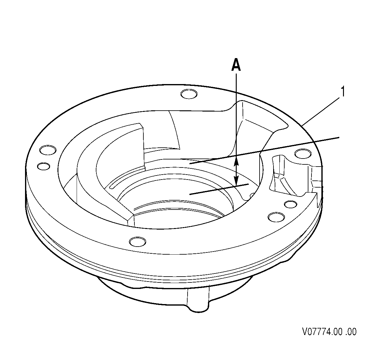
- Measure the depth of the oil pump body gear cavity at dimension A.
- Measure the ID of the oil pump body gear cavity at dimension A.
- Measure the OD of the driven gear at dimension A.
- Measure the distance between the flats of the drive gear at dimension A.
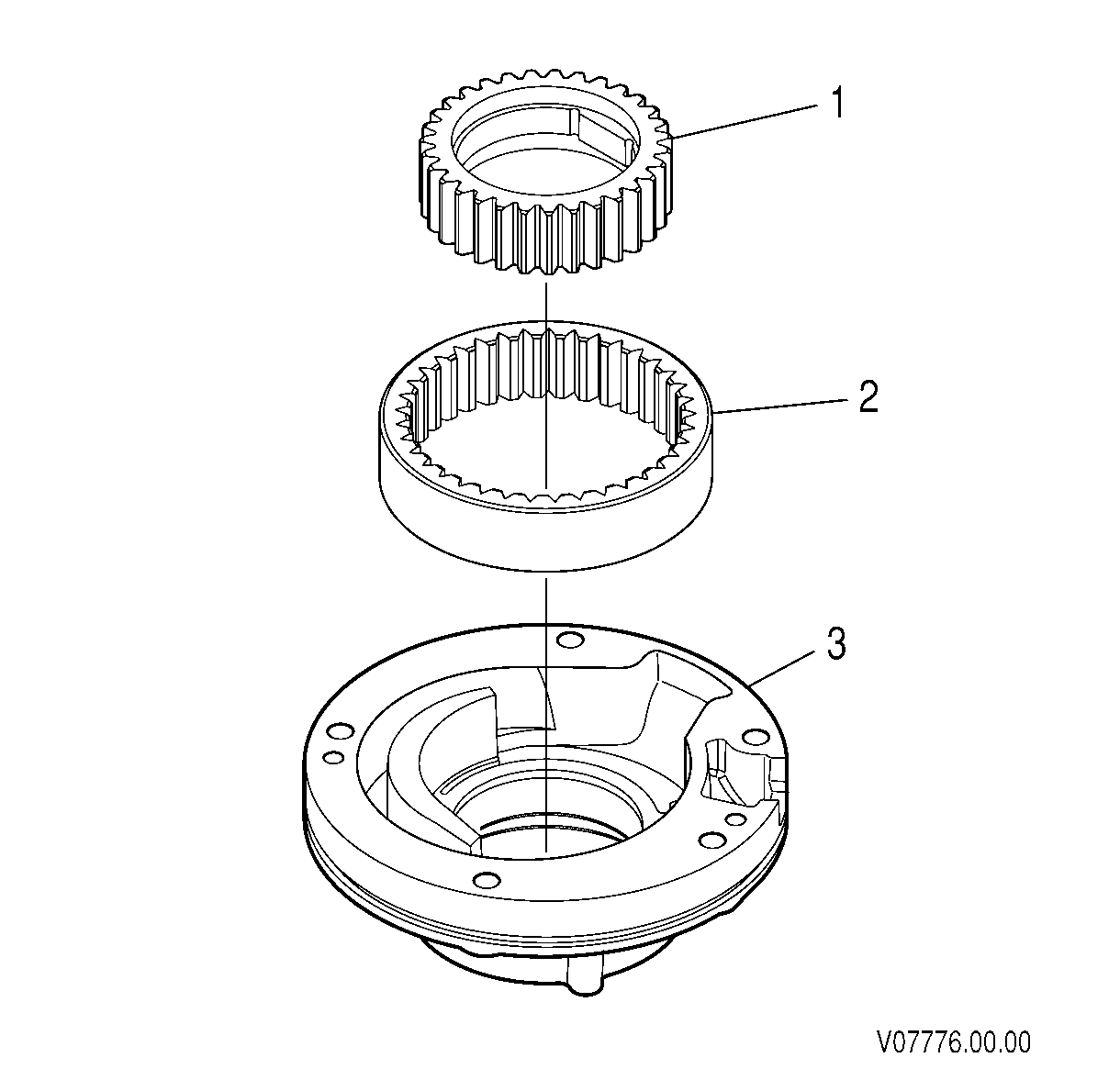
- Align the drive gear (1) and driven gear (2) with the oil pump so that their punch marks are in the same position as when they were originally removed.
- Install the gears into the oil pump body (3).
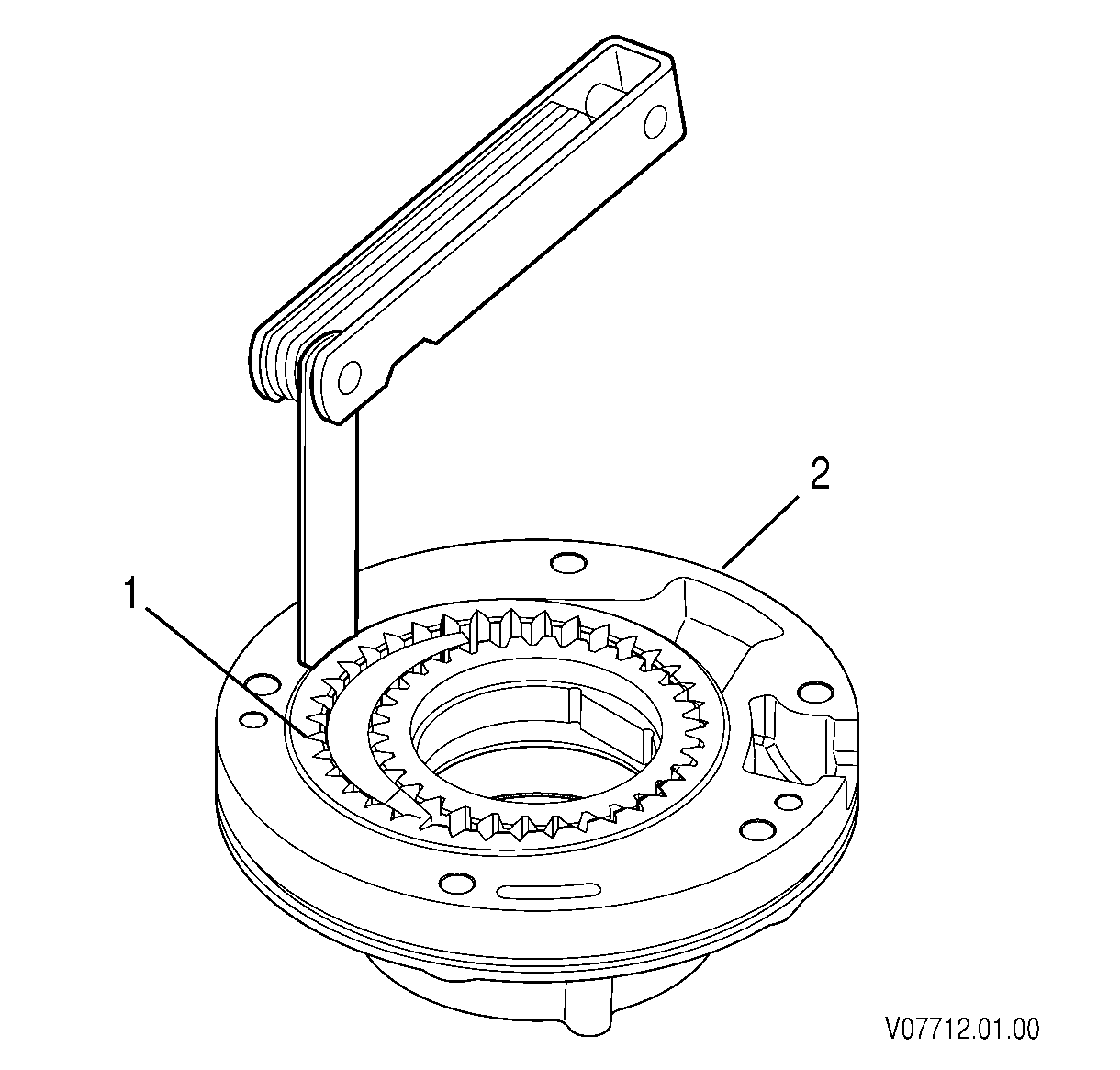
- Measure the clearance between the driven gear (1) and the oil pump body (2), driven gear diametrical clearance.
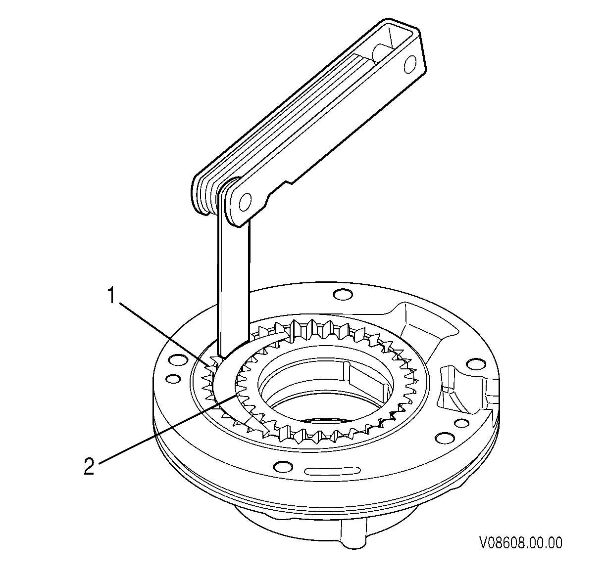
- Measure the clearance between the driven gear (1) and the oil pump body crescent (2).
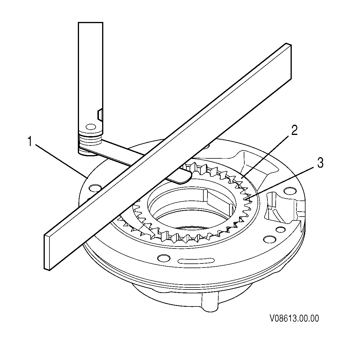
- Hold a straight edge across the oil pump body (1) and drive gear (3). Measure the clearance between the drive gear and the straight edge. This is the drive gear side clearance.
- Hold a straight edge across the oil pump body (1) and driven gear (2). Measure the clearance between the driven gear and the straight edge.
- Remove the drive gear (1) and driven gear (2) from the oil pump body (3).
Important:
• Make the measurements described below at several locations. • Replace the oil pump body, driven gear and drive gear if any of the following
specifications are not met.
Gear Cavity Depth
The maximum depth of the gear cavity is
24.940 mm (0.9819 in).
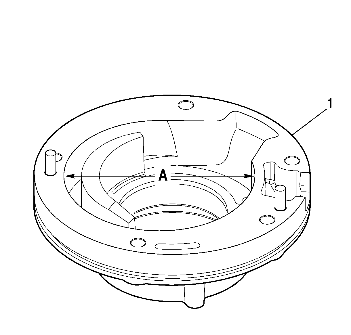
Gear Cavity ID
The maximum ID of the gear cavity is 109.191 mm
(4.2989 in).
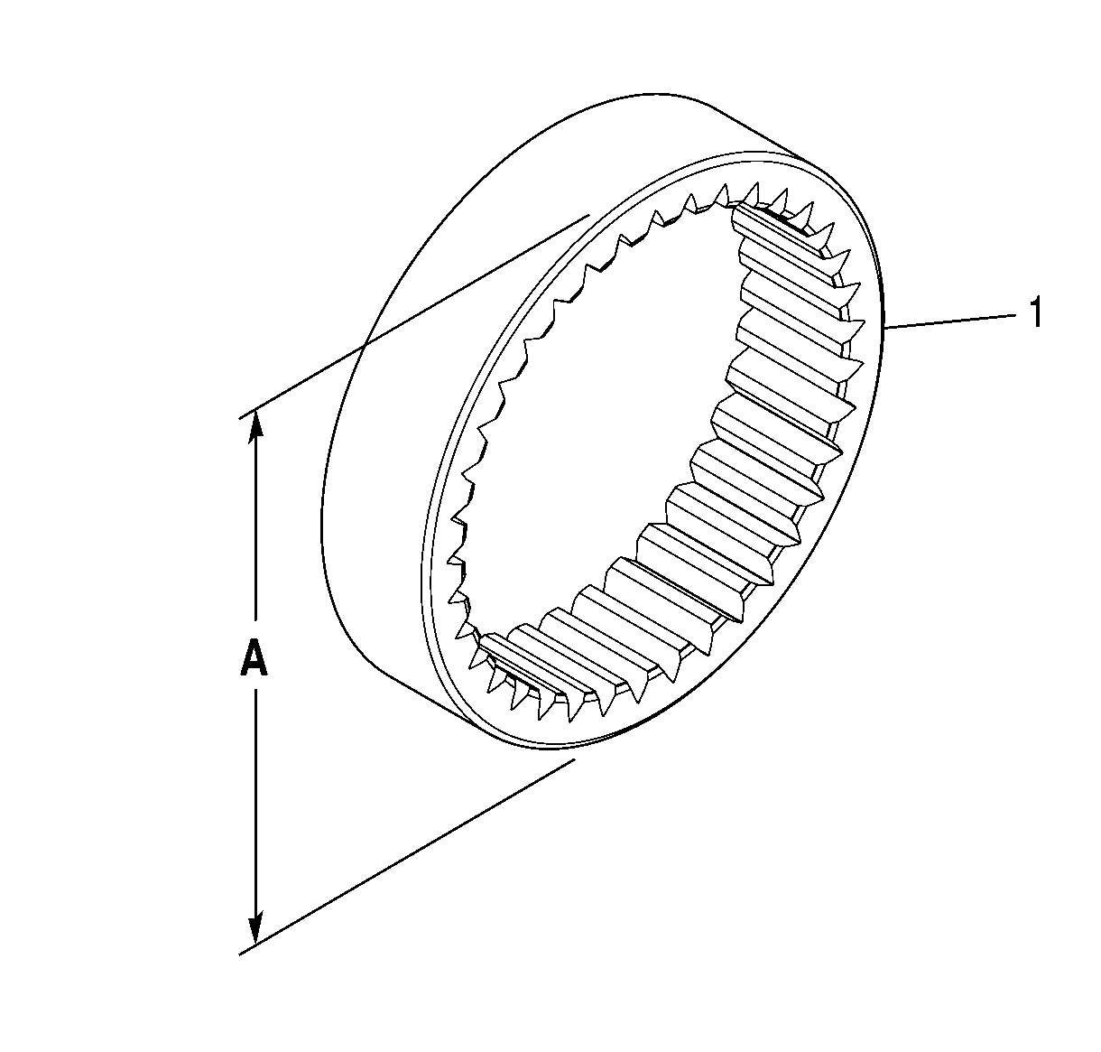
Driven Gear OD
The minimum OD of the driven gear is 108.987 mm (4.2908 in).
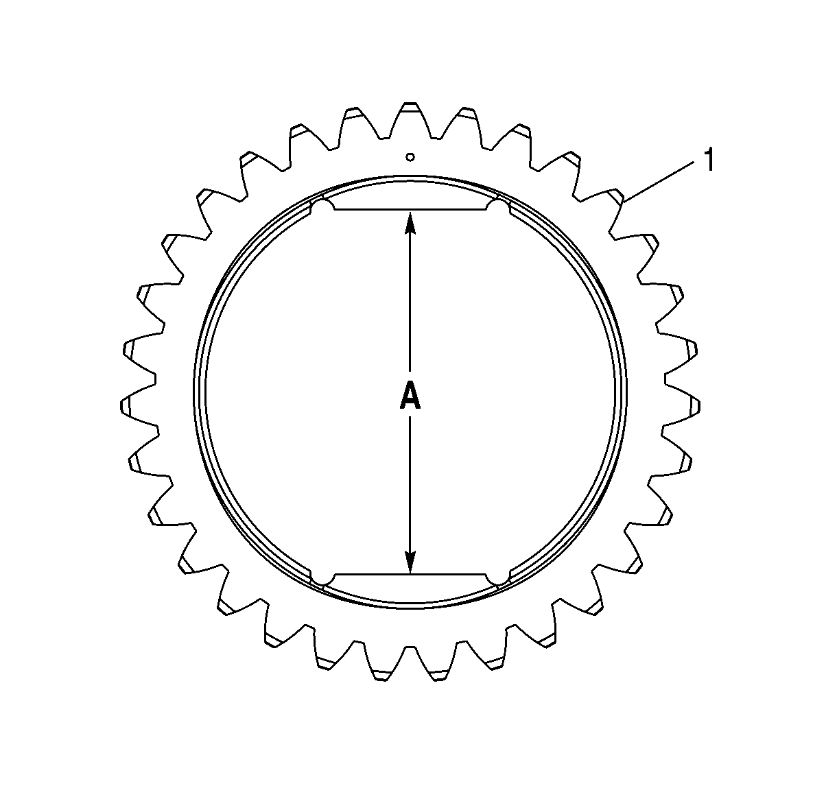
Drive Gear Flat Measurement
The maximum distance between
the flats is 52.165 mm (2.0537 in).
Driven Gear Diametrical Clearance
The maximum driven gear
diametrical clearance is 0.20 mm (0.0080 in).
Driven Gear/Crescent Clearance
The maximum Driven Gear/Crescent
Clearance is 0.455 mm (0.0179 in).
Drive Gear Side Clearance
The maximum drive gear side clearance
is 0.066 mm (0.0026 in).
Driven Gear Side Clearance
The maximum driven gear side
clearance is 0.050 mm (0.0022 in).

Oil Pump Wear Plate Inspection
- Inspect the wear plate (1) for damage. The wear plate must not be scored, nicked, or grooved.
- Measure the thickness of the wear plate in the gear wear area.
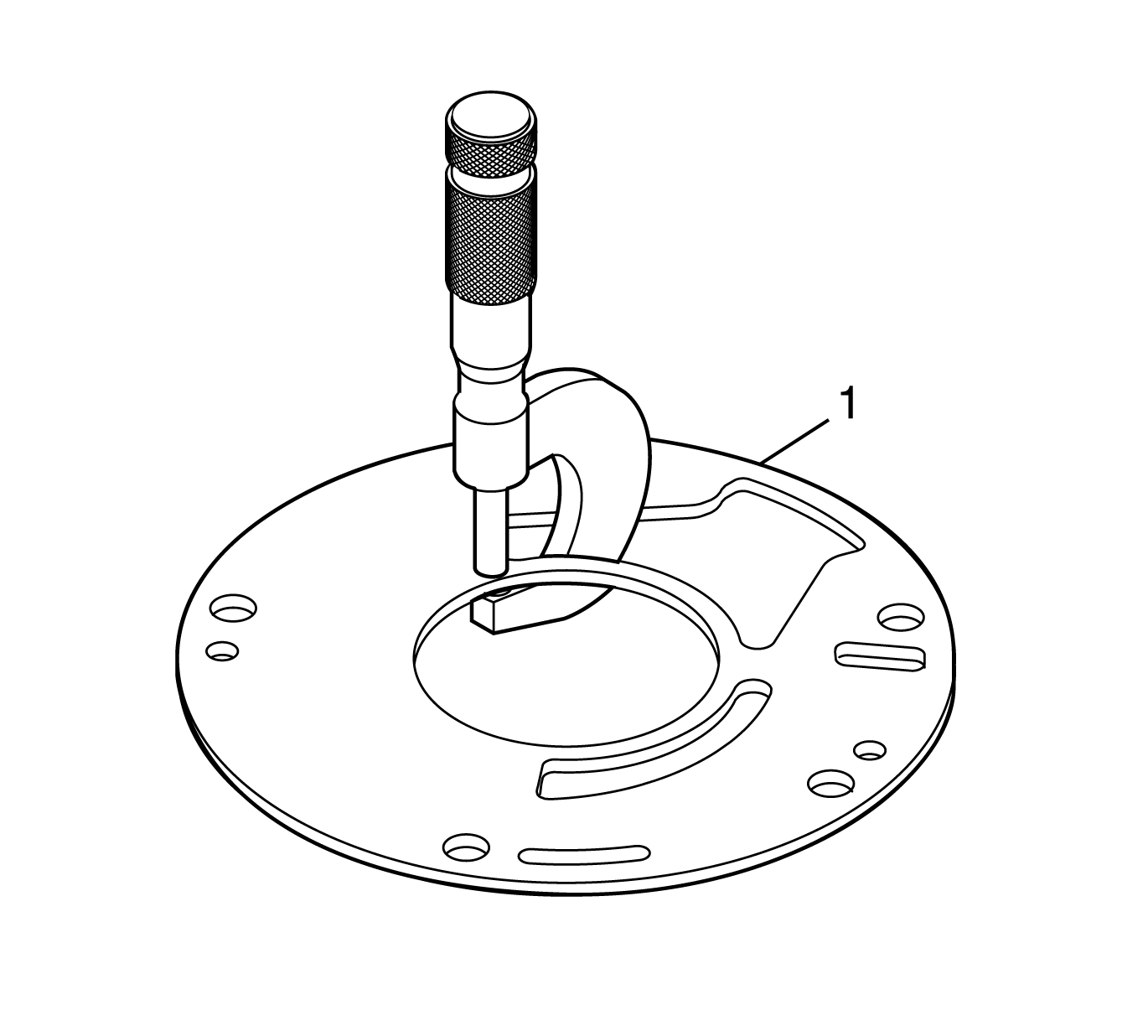
Important: Replace the oil pump wear plate if specifications are not met.
Wear Plate Thickness
The thickness of the wear plate must
not be less than 2.950 mm (0.116 in).
Oil Pump Bushing Replacement
Tools Required
| • | J 43771 Pump Bushing Removal and Installation Tool |
| • | J 8092 Universal Driver |
- Inspect the bushing for damage and wear. The bushing must not be damaged or worn.
- Measure the ID of the bushing. Replace the pump bushing if the ID exceeds specifications.
- Remove all gears from pump body (1).
- Support the pump body (1), machined surface up, on two wooden blocks so that bushing (2) can be removed from the back of the pump body.
- Install the longer end of J 43771 into the bushing.
- Press or drive the bushing (2) from the pump body (1).
- Clean the bushing bore of all residue. Parts must be dry before installing the bushing.
- Support the pump body (1), machined surface down, on two wooden blocks.
- Install the bushing (2) onto the shorter end of J 43771 .
- Apply Loctite® #620, or equivalent, to the bushing bore.
- Using J 43771 , press or drive the bushing into the pump body until J 43771 seats.
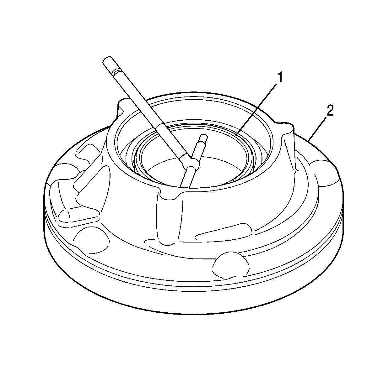
Bushing ID
Maximum ID is 58.458 mm (2.3015 in).
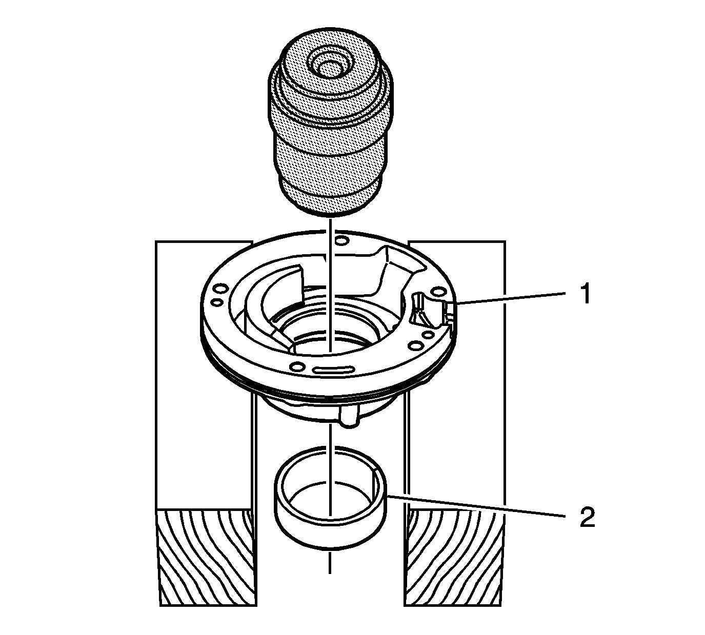
Important: The preferred method of removing or installing the bushing is with tool J 43771 and a press. If a press is not available use J 43771 and universal driver J 8092 .
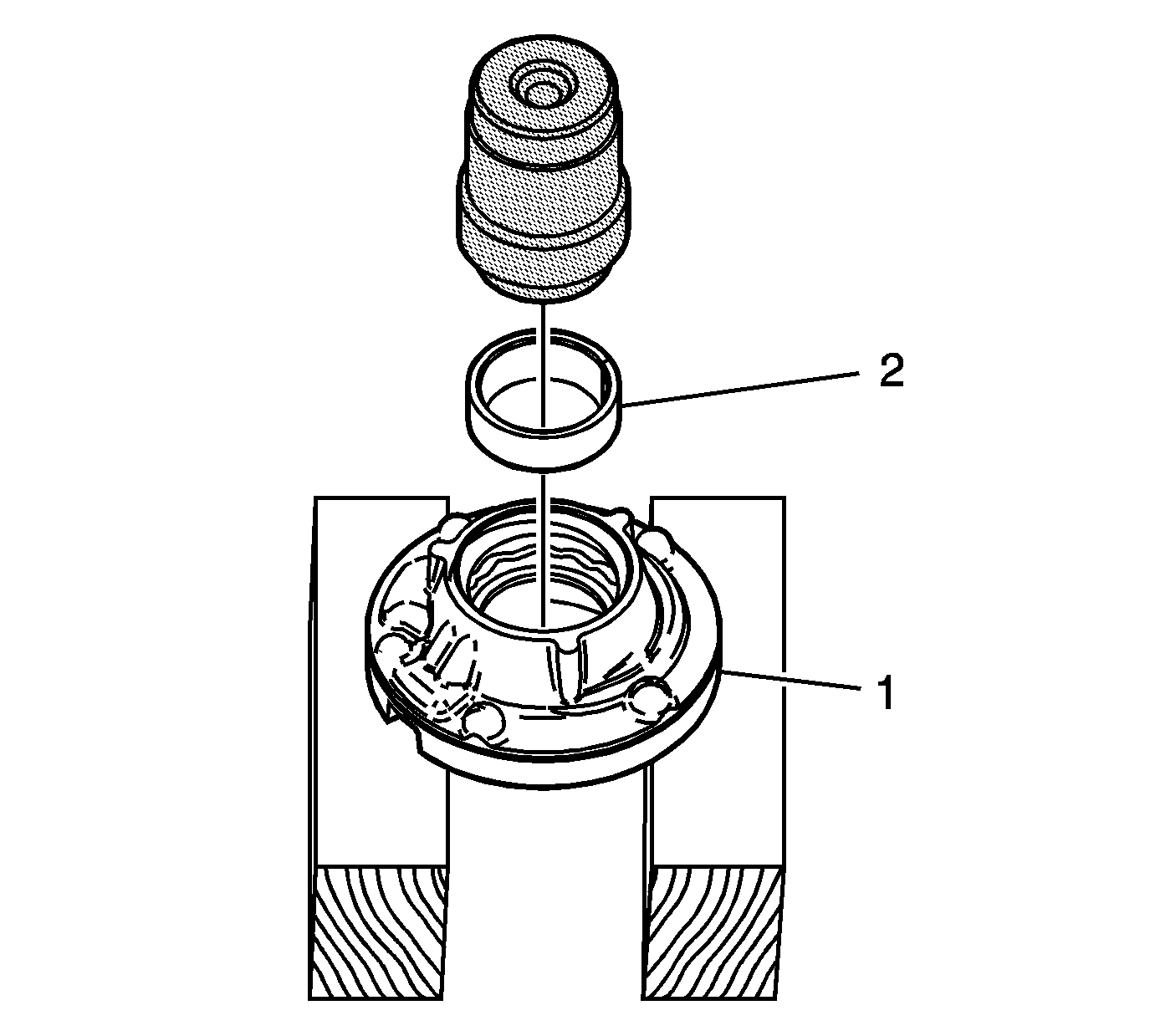
Important: The bushing may be orientated in any position, but the preferred orientation is with the bushing split joint aligned with the casting numbers and the centerline of the boss opposite the numbers. Position the split joint away from the boss.
