For 1990-2009 cars only
Exhaust Gas Recirculation Coolant Hoses/Pipes Replacement 6.6L (LLY) Engine
Removal Procedure
- Remove the intake manifold cover. Refer to Intake Manifold Cover Replacement .
- Remove the air cleaner outlet duct. Refer to Air Cleaner Outlet Duct Replacement .
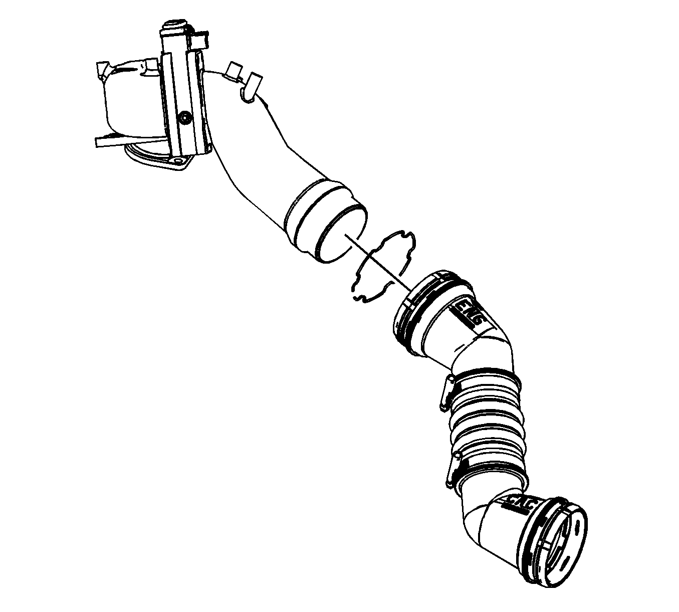
- Using a pick or a small flat-bladed screw driver, remove and discard the quick connect fitting clip from the charged air cooler outlet duct.
- Remove the charged air cooler outlet duct from the intake.
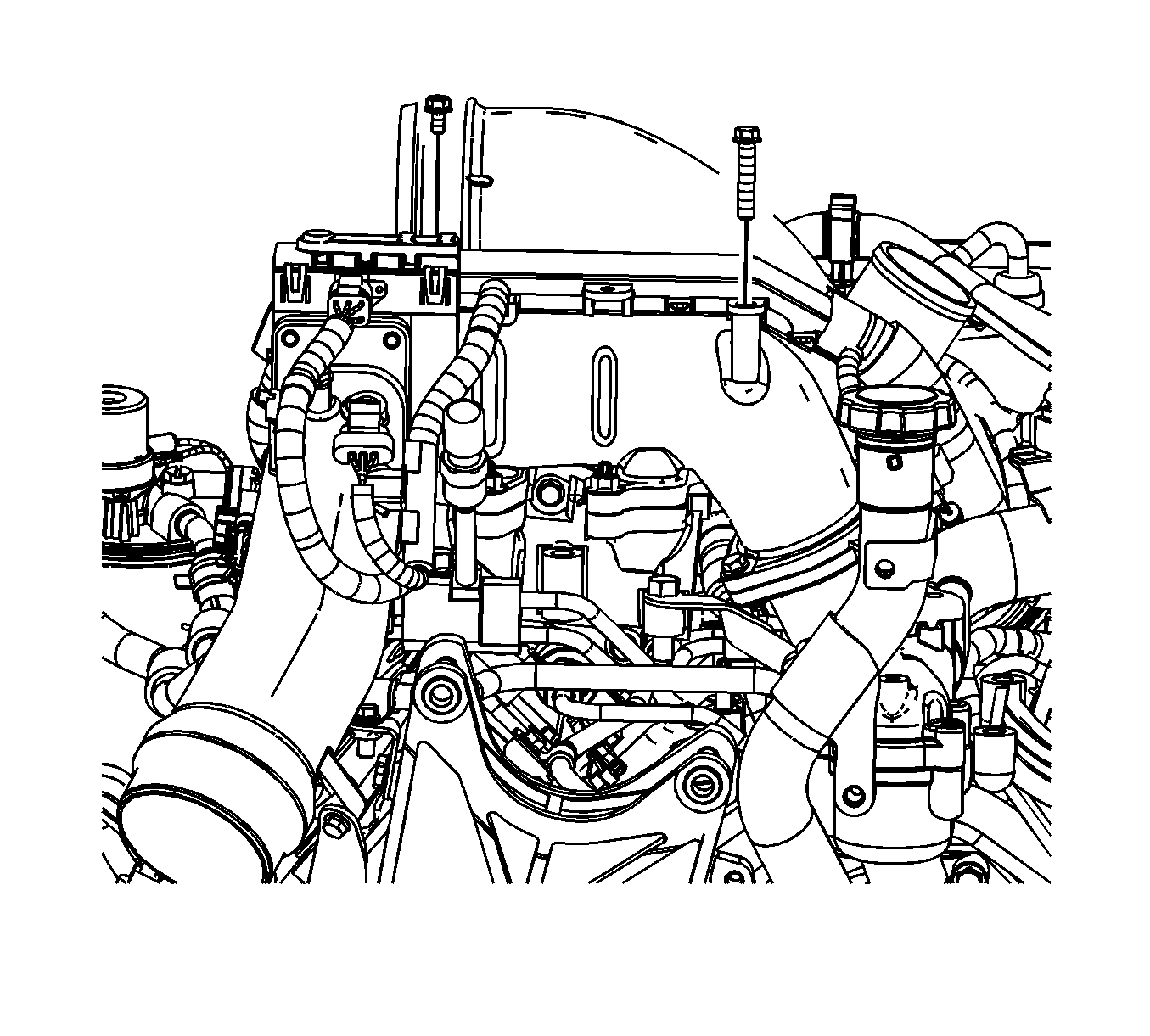
- Remove the electrical harness bolts.
- Reposition the engine harness from the air inlet tube.
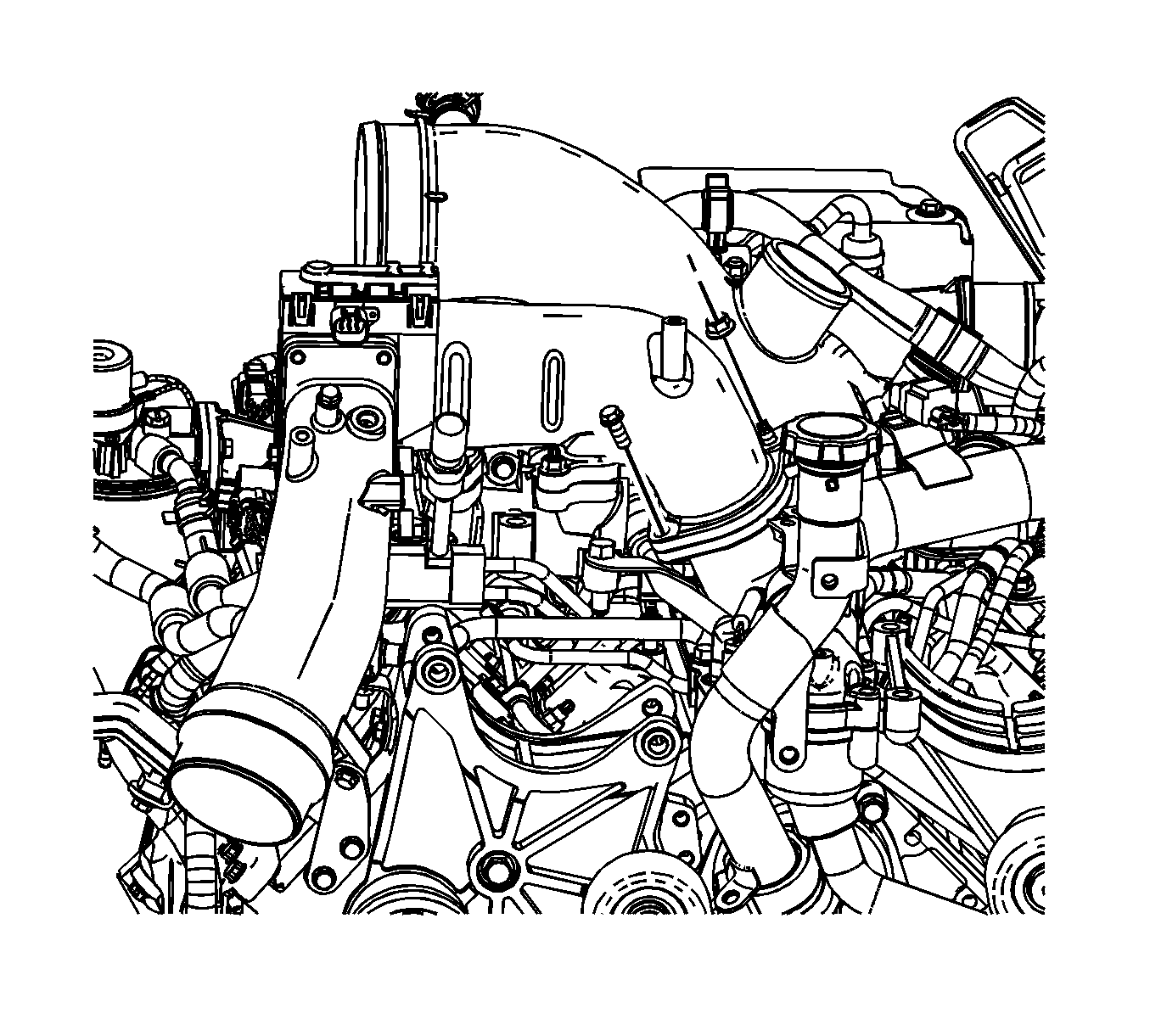
- Remove the air inlet tube to intake manifold tube bolt and nut.
- Disconnect the air intake heater electrical connector.
- Disconnect manifold absolute pressure (MAP) sensor electrical connector.
- Remove the engine harness clip from the air inlet tube.
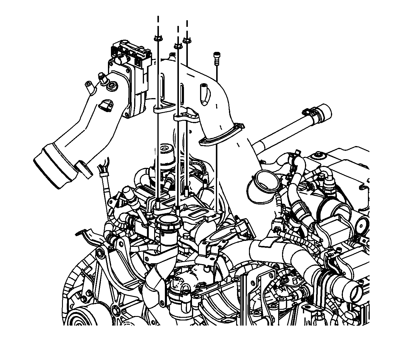
- Remove the air inlet tube nuts.
- Remove the air inlet tube.
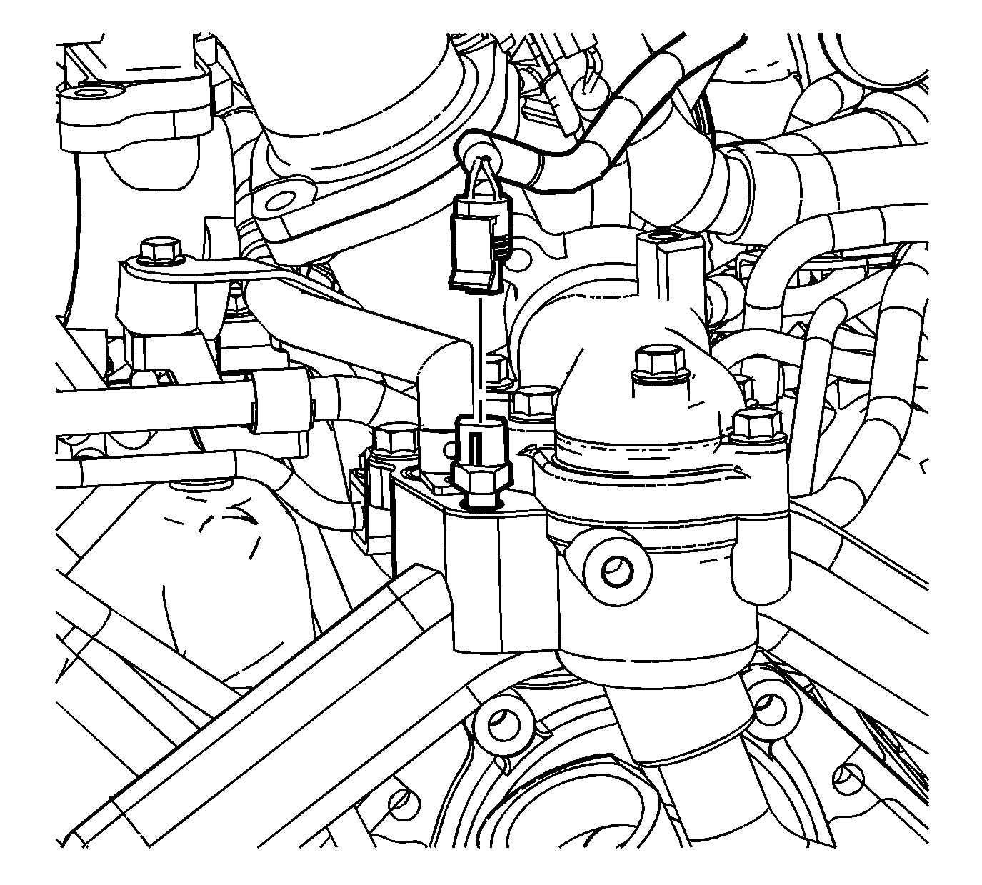
- Disconnect the engine coolant temperature (ECT) sensor electrical connector.
- Reposition the exhaust gas recirculation (EGR) coolant pipe hose clamp.
- Remove the EGR coolant pipe hose.
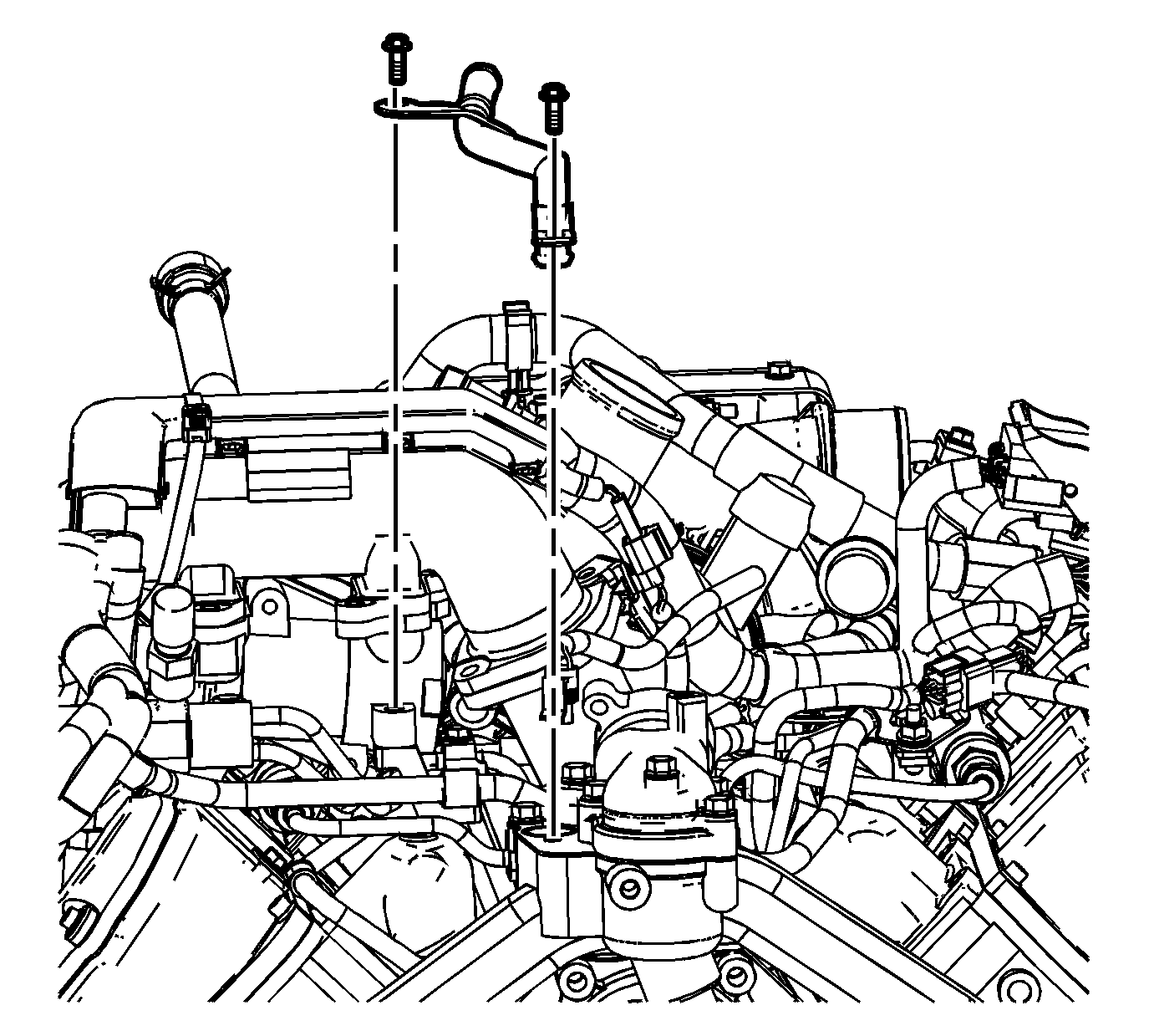
- Remove the EGR coolant pipe bolts.
- Remove the EGR coolant pipe.
- Remove and discard the coolant pipe O-ring seal.
Installation Procedure
- Install a NEW O-ring seal onto the coolant pipe. Lubricate the seal with engine coolant.
- Install the EGR coolant pipe.
- Install the EGR coolant pipe bolts.
- Install the EGR coolant pipe hose.
- Position the EGR coolant pipe hose clamp.
- Connect the ECT sensor electrical connector.
- Install the air inlet tube.
- Install the air inlet tube nuts.
- Connect the air intake heater electrical connector.
- Connect MAP sensor electrical connector.
- Install the engine harness clip to the air inlet tube.
- Install the air inlet tube to intake manifold tube bolt and nut.
- Position the engine harness to the air inlet tube.
- Install the engine harness bolts.
- Install a NEW quick connect fitting clip to the charged air cooler duct.
- Install the charged air cooler outlet duct to the intake.
- Install the air cleaner outlet duct. Refer to Air Cleaner Outlet Duct Replacement .
- Install the intake manifold cover. Refer to Intake Manifold Cover Replacement .

Notice: Refer to Fastener Notice in the Preface section.
Tighten
Tighten the bolts to 25 N·m (18 lb ft).


Tighten
Tighten the nuts to 25 N·m (18 lb ft).

Tighten
Tighten the bolt/nut to 10 N·m (89 lb in).

Tighten
Tighten the bolts to 4 N·m (35 lb in).

