LOSS OF PWR. DUE TO VAPOR LOCK (INSTALL NEW VAPOR LOCK KIT)

SUBJECT: LOSS OF POWER DUE TO VAPOR LOCK
MODELS: 1985-88 MEDIUM DUTY B6P042 EQUIPPED WITH GASOLINE ENGINES AND 30/60 GALLON FUEL TANK (NH2/NH9)
Some 1985-1988 subject model vehicles may experience an intermittent loss of engine power due to fuel line vapor lock when operated during high ambient temperatures and/or heavy load conditions.
Listed below are some of the conditions experienced when vapor lock occurs:
1. Loss of engine power when hot, but operates properly after sitting several hours or overnight.
2. Engine will not continue to run when hot.
3. Long starter crank times when attempting to start a hot engine.
Vapor lock occurs when fuel in the line vaporizes. Because the engine mechanical fuel pump is actually a liquid suction pump, when this condition occurs the fuel pump efficiency may be greatly reduced or the pump may become inoperative. One way to eliminate the effects of vapor lock is to push the fuel to the engine mechanical fuel pump with an electric pump.
Service has released an in-tank electric fuel pump kit which incorporates an electric pump, fuel gage sender, wiring harness and an electric pump/control module. This will increase the performance of the engine when operated in high ambient temperatures or under heavy load conditions.
IMPORTANT: This change will provide engine alarm system on vehicles pre- viously not equipped with (X54) alarm system.
To eliminate the vapor lock condition, the modification will require the ordering and installation of three (3) separate part numbers which are determined by the vehicle RPO content. These three (3) separate parts are listed below:
1. Fuel Tank Sender Assembly
2. Electric Pump Assembly
3. Vapor Lock Installation Kit
Adequate care must be used when ordering parts to insure proper installation and results. See parts list contained in this bulletin.
SERVICE PROCEDURE
1. IN-TANK FUEL PUMP INSTALLATION --------------------------------- Listed below are three separate service procedures which can be used to remove/install electric in-tank fuel pumps, depending on the bus body, fuel tank capacity, and wheel base.
CAUTION:
To prevent a fire and personal injury when working on the fuel system, disconnect the vehicle battery ground (-) cable(s) and be sure fire fighting and safety equipment as required by any local fire and safety regulations and dealership policies are available.
A. IN-TANK PUMP INSTALLATION IF BUS BODY IS EQUIPPED WITH A FUEL TANK SENDING UNIT ACCESS HOLE
1. Remove four screws and access plate (plate may be secured to the floor with sealer and may have to be pried loose).
2. Disconnect fuel sender wire and fuel lines.
3. Remove seven mounting screws, washers and mounting ring from sender and retain.
4. Remove sender and gasket from tank and discard.
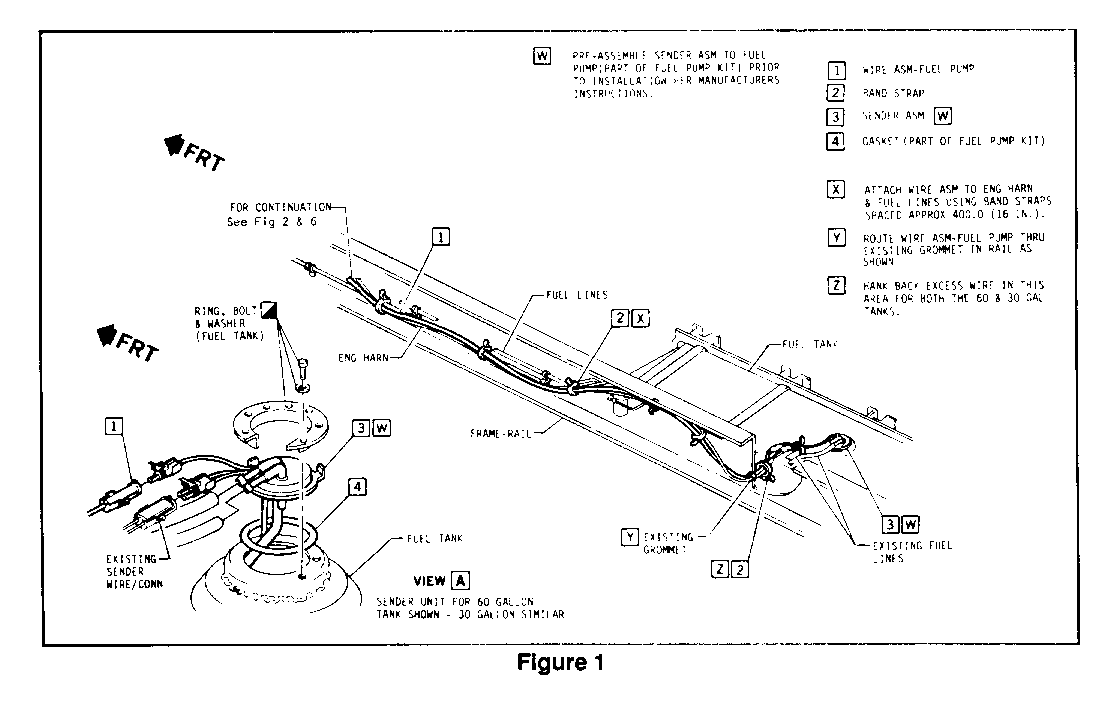
5. Clean gasket mounting area thoroughly and install new gasket (4) (Figure 1).
6. Follow instructions supplied for assembly of fuel pump to sending unit and then install sender/pump assembly. Reinstall mounting screws, washers and mounting ring (Figure 1).
7. Route one end of fuel pump feed wire (1) from service kit through existing wiring grommet in frame and connect to sender/pump connector (3) (Figure 1).
8. Reinstall cover plate using sealer between plate and floor.
B. IN-TANK PUMP INSTALLATION ON VEHICLES WITH THE FOLLOWING OPTIONS WITHOUT BODY ACCESS HOLE:
60 gallon fuel tank (NH9) and 254" (FQB) or 274" (FD2) wheel base.
30 gallon fuel tank (NH2) and 189" (FWS), 218" (FPL), 235" (FRP), 254" (FQB) or 274" (FD2) wheel base.
1. Drain fuel from fuel tank.
2. Remove fuel line bracket and grommets in frame at fuel sender location (Figure 1).
3. Pull lines through frame until clamps are accessible. Remove clamps and disconnect hoses.
4. If sender wires cannot be disconnected, cut sender wires at easily accessible point inside of frame channel.
IMPORTANT: These wires will have to be spliced together again upon reinstallation of tank.
5. Disconnect fuel tank vent valve from bracket at tank. This valve is secured with rose bud clips which must be compressed to slip valve out of bracket.
6. Remove outboard nuts securing the four tank mounting straps and pull studs out of mounting holes.
7. For 60 gallon tank, totally remove the two inside straps from tank by removing cotter pins and clevis pins from inboard side.
8. Remove four cotter pins and clevis pins from horizontal mounting strut at rear of tank. Remove nuts and bolts at inboard side and remove strut.
9. Slide tank out of saddle brackets to rear of vehicle on 60 gallon tank. Tank must be lifted up and tilted at outboard side so drain plug at bottom can clear saddle brackets and so vents on top of tank can clear the floor braces.
IMPORTANT: Two technicians may be required for Step #9.
10. Remove seven mounting screws, washers and mounting ring from sender and retain.
11. Remove sender and gasket and discard. Save old connector and wires which were cut off at Step 4.
12. Clean gasket mounting area thoroughly and install new gasket (4) (Figure 1).
13. Follow instructions supplied for assembly of fuel pump to sending unit and then install sender/pump assembly in fuel tank (3). Reinstall mounting screws, washers and mounting rings (Figure 1).
14. Connect existing engine harness sender connector to new sender/pump connector (3). Wires win be spliced when tank is reinstalled (Figure 1).
15. Route one end of fuel pump feed wire (1) from service kit through existing wiring grommet in frame (Figure 1).
16. Slide fuel tank back into brackets for 60 gallon tank. Tank must be tilted up at outboard edge at last two brackets to clear gussets.
17. Reconnect fuel lines and install grommets (Figure 1).
18. If sender wires were cut, splice wires back together. Use staggered splice clips and double wrap securely with vinyl tape.
19. Center tank properly in brackets and reinstall tank rear end support bracket.
20. Reinstall two inside tank mounting straps on 60 gallon tank.
21. Reinstall nuts on tank mounting straps. Torque to 39-50 Nm (29-37 lbs/ft).
C. IN-TANK PUMP INSTALLATION ON VEHICLES WITH FOLLOWING OPTIONS WITHOUT BODY ACCESS HOLE:
60 gallon fuel tank (NH9) and 149" (FXV), 189" (FWS), 218" (FPL), and 235" (FRP) wheelbase.
30 gallon fuel tank (NH2) and 149" (FXV) wheelbase.
1. Drain fuel from fuel tank.
2. Remove fuel line bracket and grommets in frame at fuel sender location (Figure 1).
3. Pull Lines through frame until clamps are accessible. Remove clamps and disconnect hoses.
4. If necessary, install a jack and wooden blocks under fuel tank for support. It may be necessary to remove the two center skid plates from under the tank to properly balance the tank on the center of jack.
5. Remove and retain the 4 nuts, bolts and washers holding the fuel tank mounting brackets to the frame. There are three brackets for the 30-gallon tank and five brackets for the 60-gallon tank. Remove vent filter bracket with front mounting bracket.
6. Remove the 4 clevis pins and cotter pins from outer ends of horizontal mounting struts on front and rear of tank.
7. Carefully lower tank sufficiently to gain access to fuel sender unit.
8. Disconnect fuel sender unit wire at tank unit.
9. Slide fuel tank outboard from frame if necessary for access to sender unit.
10. Remove seven mounting screws, washers and mounting ring from sender and retain.
11. Remove sender and gasket and discard.
12. Follow instructions supplied for assembly of fuel pump to sending unit and then install sender/pump assembly in fuel tank (3). Reinstall mounting screws, washers and mounting rings (Figure 1).
IMPORTANT: Sender and fuel pump is not included in vapor lock kit. It will be necessary to order these separately.
13. Connect existing engine harness sender connector to new sender/pump connector (3) (Figure 1).
14. Route one end of fuel pump feed wire (1) from service kit through existing wiring grommet in frame (Figure 1).
15. Jack up tank and mounting brackets to proper height for mounting.
16. Reconnect fuel lines, fuel line bracket or clip and reinstall grommets (Figure 1).
17. Reattach mounting brackets to frame with existing hardware along with vent filter bracket. Torque nuts to 61-68 Nm (45-50 lbs/ft).
After the sending unit and fuel pump has been installed, follow the applicable procedures listed below to complete the installation of the vapor lock kit.
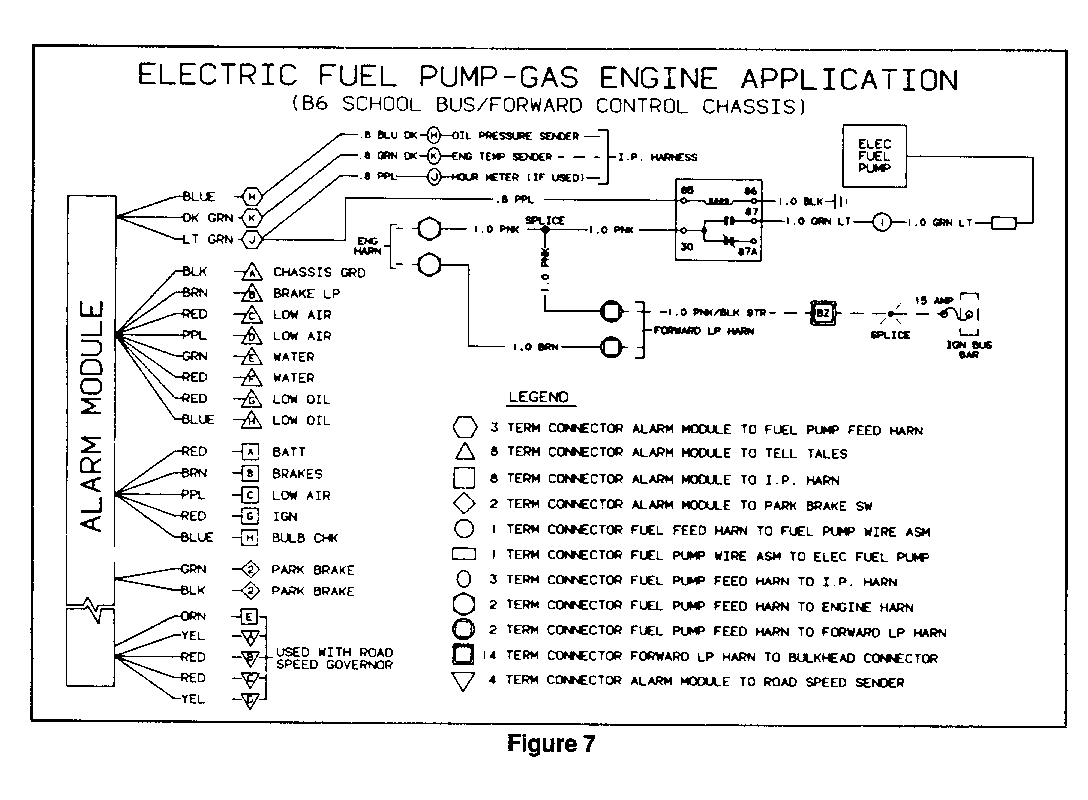
2. ELECTRICAL MODULE ASSEMBLY REPLACEMENT (FIGURES 1 THRU 7) ------------------------------------------------------------ IMPORTANT: Figure 7 will assist in the assembly of the electrical module.
Listed below are two separate replacement procedures, depending if the vehicle is equipped with RPO RQ2 (school bus application), IBMA (non- school bus application) or IBNW (stripped chassis).
A. ELECTRICAL MODULE REPLACEMENTS AND FUEL PUMP WIRE ASSEMBLY INSTALLATION-FOR RPO RQ2 (COWL MODEL/SCHOOL BUS APPLICATION) OR RPO IBMA (COWL MODEL/NON-SCHOOL BUS APPLICATION)
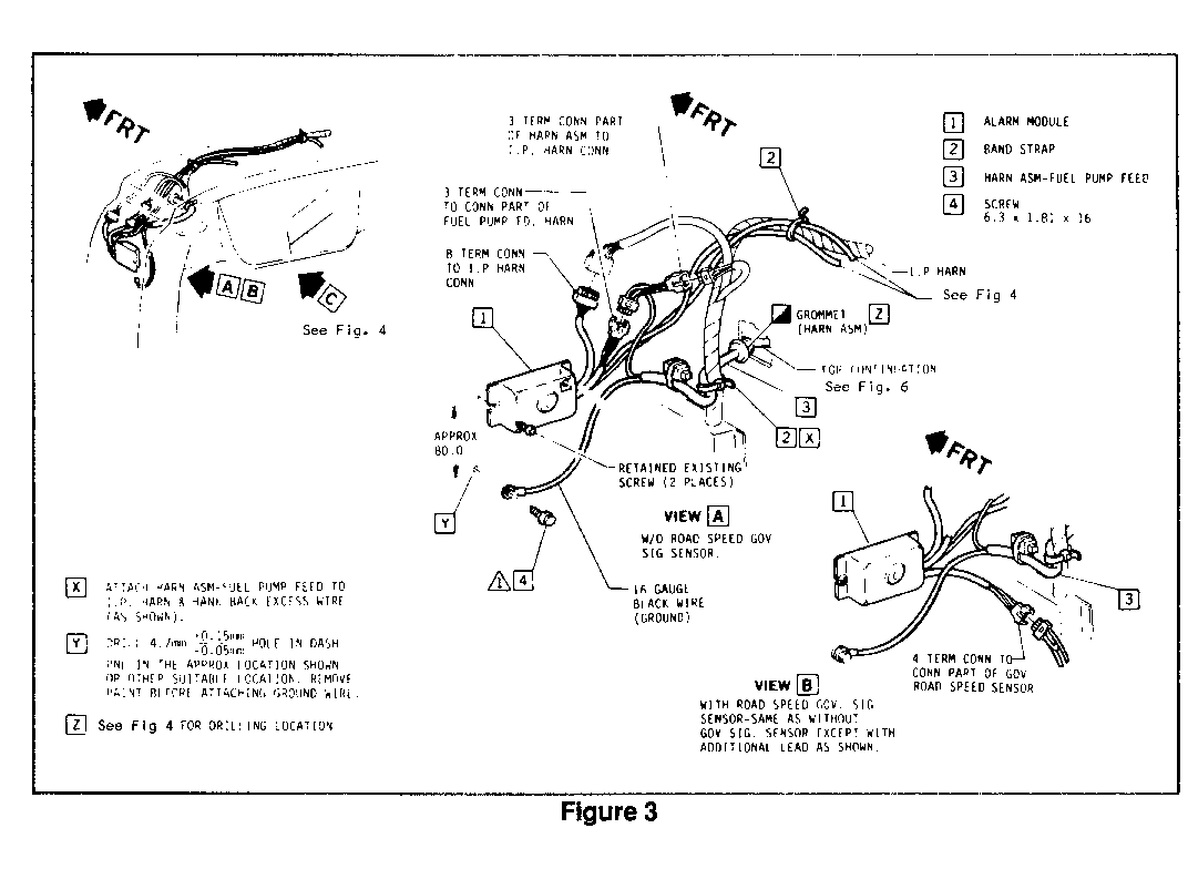
1. Unplug two existing alarm module assembly connectors from instrument panel harness connectors. Also unplug parking brake switch connector (hydraulic brakes only), tell-tale asm connector and road speed governor connector if equipped (Figure 3).
2. Install new alarm module from service kit with existing screws.
3. Connect fuel pump feed harness connectors as follows:
a. Module connector (3-way female) to module assembly.
b. Instrument panel connector (3-way male) to instrument panel harness.
IMPORTANT: Connector may be taped back to body harness for vehicles without engine alarm (x54).
4. Connect remaining module connectors as follows:
a. Instrument panel connector (8-way female) to instrument panel harness.
b. Park brake connector (2-way male) to park brake switch jumper harness (hydraulic brakes only).
c. Tell-tale (8-way) connector to tell- tale.
d. Connect road speed governor (4- way).
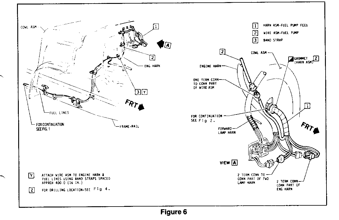
5. Disconnect engine and forward lamp harness connectors (2-way weather packs) and connect fuel pump feed harness 2- way connectors between them (Figure 6).
6. Tie-wrap fuel pump feed harness (2) to instrument panel harness and tie back excess wire. Tie-wrap alarm module wiring to instrument panel wiring in two places.
7. Connect fuel pump feed wire (1) to sender/pump assembly (3) (Figure 1).
8. Route fuel pump wire assembly from fuel tank to cowl (Figures 1 and 3).
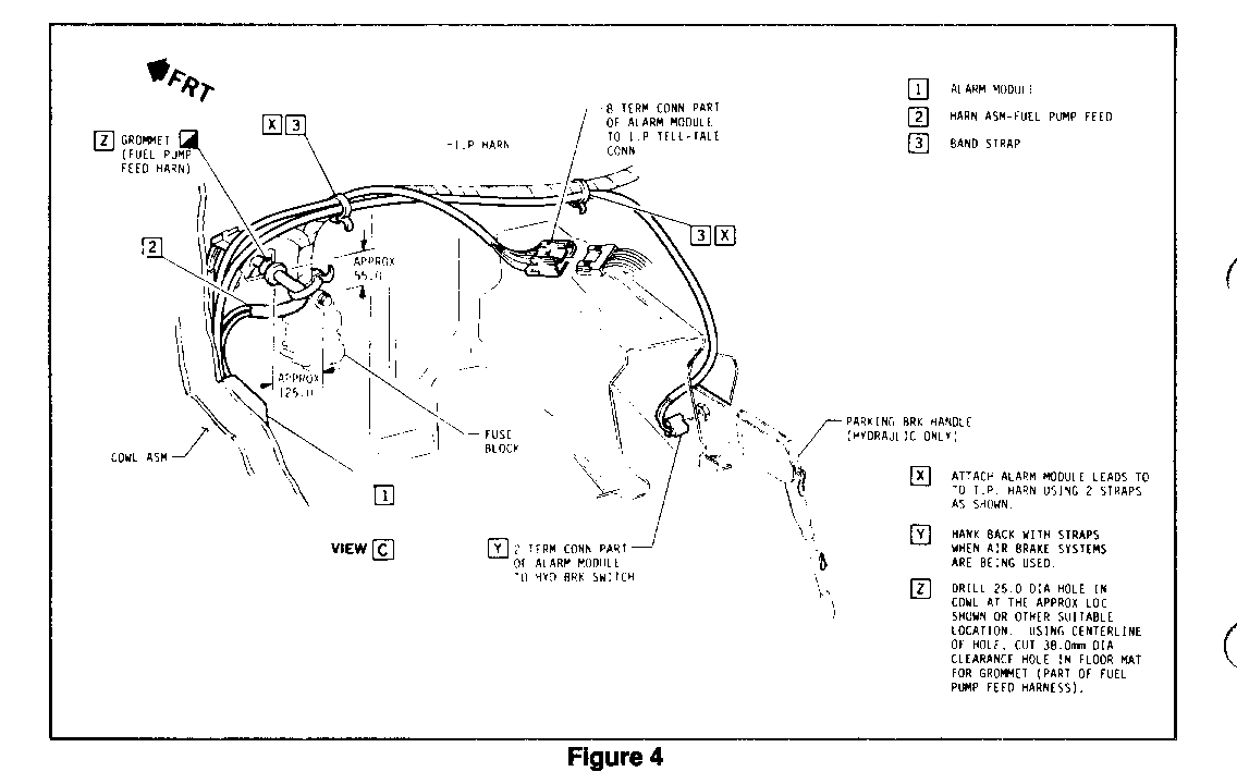
9. Attach fuel pump wire assembly to existing harness with the 20 band straps provided in the service kit. Space straps approximately 400mm (16 inches) apart. If there is excess length in wire assembly, tie back excess and band strap to body of existing harness (Figure 4).
10. Attach connector on fuel pump wire assembly to fuel pump harness connector (Figure 6).
B. ELECTRICAL MODULE REPLACEMENT AND FUEL PUMP WIRE ASSEMBLY INSTALLATION WITH RPO IBNW (STRIPPED CHASSIS/ISLAND)
1. Unplug two existing alarm module assembly connectors from instrument panel harness connectors. Also unplug parking brake switch connector (hydraulic brakes only), tell-tale asm connector and road speed governor connector if equipped (Figure 3).
2. Remove two screws holding alarm module to control island dash panel. Dis- card alarm module and retain screws.
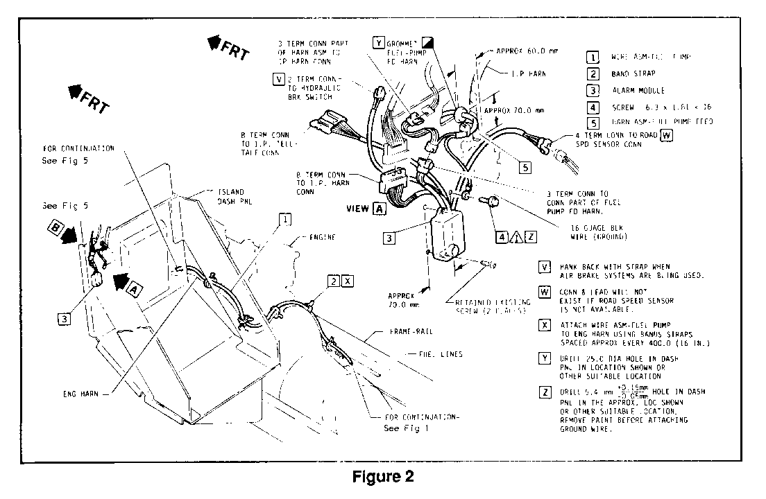
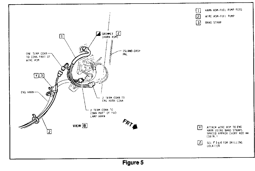
3. Drill a 25.0 mm hole in control island dash panel (Figure 2) or cowl (Figure 4) and insert fuel from pump feed harness through hole from side to engine compartment and seat feed harness grommet.
IMPORTANT: All holes drilled in control island must be clear of all components and reinforcement panels.
If vehicle has cowl, drill a 38.0 mm hole in floor mat to clear grommet (Figure 4).
4. Install new alarm module from service kit with existing screws (Figure 2).
5. Connect fuel pump feed harness connectors as follows:
a. Module connector (3-way female) to module assembly.
b. Instrument panel connector (3-way male) to instrument panel harness.
6. Connect remaining module connectors as follows:
a. Instrument panel connector (8-way female) to instrument panel harness.
b. Park brake connector (2-way male) to park brake switch jumper harness (hydraulic brakes only).
c. Tell-tale (8-way) connector to tell-tale.
7. Install ground wire (16-gauge black) ring terminal as follows:
a. Drill a 5.4 mm hole in control island dash.
b. Clean surface of paint.
c. Screw ground wire down and torque to 3.4-4.6 Nm (30-40 lbs/in).
8. Disconnect engine and forward lamp harness connectors (2-way weather packs) and connect fuel pump feed harness 2-way connectors between them (Figure 5).
9. Connect fuel pump feed wire (1) to sender/pump assembly (3) (Figure 1).
10. Route fuel pump wire assembly from fuel tank to cowl or control island area with the engine harness (Figure 2).
11. Attach fuel pump wire assembly to existing harness with the 20 band straps provided in the service kit. Space straps approximately 400mm (16 inches) apart. If there is excess length in wire assembly, tie back excess and band strap to body of existing harness (Figure 1).
12. Attach connector on fuel pump wire assembly to fuel pump harness connector at control island area (Figure 5).
4. FINAL INSPECTION AND TEST ---------------------------- A. Reconnect battery ground cable.
B. Reinstall tank drain plug.
C. Refill tank with fuel and operate pump.
IMPORTANT: To check if in-tank fuel pump is operating properly, it will be necessary to disconnect fuel line at tank and check for flow, since mechanical pump is still operational.
D. Check fuel lines and drain plug for leakage.
PARTS INFORMATION
To make above change, three (3) parts must be ordered as listed below:
* Fuel Tank Sender Assembly
* Electric Pump Assembly
* Vapor Lock Installation Kit/Electrical Harness (based on vehicle RPO content)
PART NUMBER DESCRIPTION APPLICATION QTY ------ ----------- ----------- --- 25094477 Sender Assembly (NH9) B-6 Models 1 60 Gallon
25094470 Sender Assembly (NM) B-6 Models 1 30 Gallon
25115955 Electric Pump Assy. All B-6 Models 1
15625343 Installation Kit All B-6 without Road Speed Governor 1
15625345 Installation Kit AH B-6 with RPO VND (Max 50 mph Road Speed Governor) 1
15625347 Installation Kit All B-6 with VNE (Max 55 mph Road Speed Governor) 1
15625349 Installation Kit AU B-6 with VNF (Variable 35-55 mph Road Speed Governor) 1
Parts are currently available from GMSPO.
For repairs performed under warranty, use the applicable labor operation listed below:
For vehicles equipped with sending unit access hole in bus body: T 7635, 2.2 hrs.
For vehicles not equipped with sending unit access hole in bus body: T7630, 4.7 hrs.
General Motors bulletins are intended for use by professional technicians, not a "do-it-yourselfer". They are written to inform those technicians of conditions that may occur on some vehicles, or to provide information that could assist in the proper service of a vehicle. Properly trained technicians have the equipment, tools, safety instructions and know-how to do a job properly and safely. If a condition is described, do not assume that the bulletin applies to your vehicle, or that your vehicle will have that condition. See a General Motors dealer servicing your brand of General Motors vehicle for information on whether your vehicle may benefit from the information.
