LOSS OF PWR. DUE TO VAPOR LOCK (INSTALL NEW VAPOR LOCK KIT)

SUBJECT: LOSS OF POWER DUE TO VAPOUR LOCK (INSTL NEW KIT)
VEHICLES AFFECTED: 1985-88 C5,6,7 TRUCKS WITH GAS ENGINES AND SINGLE 35,50,OR 60 U.S. GALLON FUEL TANKS
Some 1985-88 medium duty vehicles equipped with gasoline engines may experience an intermittent loss of engine power due to fuel line vapour lock when operated during high ambient temperatures and/or heavy load conditions.
Listed below are some of the conditions experienced when vapor lock occurs:
1. Loss of engine power when hot, but operates properly after sitting several hours or overnight.
2. Engine will not continue to run.
3. Long starter crank times when attempting to start a hot engine.
Vapour lock occurs when fuel in the line vaporizes. Because the engine mechanical fuel pump is actually a liquid suction pump, when this condition occurs the fuel pump efficiency may be greatly reduced or the pump may become inoperative. One way to eliminate the effects of vapour lock is to push the fuel to the engine mechanical fuel pump with an electric pump.
Service has released an in-tank electric fuel pump kit which incorporates an electric pump, fuel gauge sender, wiring harness and an electric pump control module. This kit will increase the performance of the engine when operated in high ambient temperatures or under heavy load conditions.
Listed below are the removal and installation instructions for the electric fuel pump kit:
IMPORTANT: Review the parts information section of this Truck Service Bulletin carefully to ensure the proper parts to make this change are ordered.
Service Procedure
A. Installation of fuel tank sender/pump.
1. Disconnect negative battery cable.
2. Drain fuel tank. Refer to Medium Duty Service Manual, Section 6C, for instructions and precautions.
3. Install a jack under the fuel tank for support. Remove and retain the nuts from the tank support strap stud bolts.
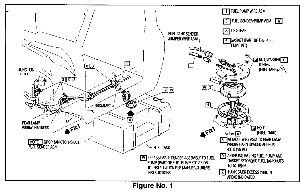
4. Disconnect the wiring harness at the fuel tank sending unit (Figure 1).
5. Slide the fuel tank outboard from vehicle and disconnect the fuel lines from the fuel sender.
6. Remove and discard the fuel tank sending unit and gasket. Save the nuts, washers and mounting ring.
IMPORTANT: The existing mechanical fuel pump is to be left on the engine.
7. Clean gasket mounting area thoroughly.
8. Install new gasket (4) and fuel sender/pump assembly (2) from kit (Figure 1).
IMPORTANT: Follow instructions supplied with kit for assembly fuel pump and sending unit before installing in tank.
9. Reinstall nuts, washers and mounting ring. Torque to 10-15 Nm.
B. Fuel Pump Feed Harness Installation
Listed below are two ways, Preferred or Optional, which the fuel pump feed harness can be routed through the cowl panel. Depending if the truck is built with regular production options or special equipment options will determine the installation of the fuel pump harness.
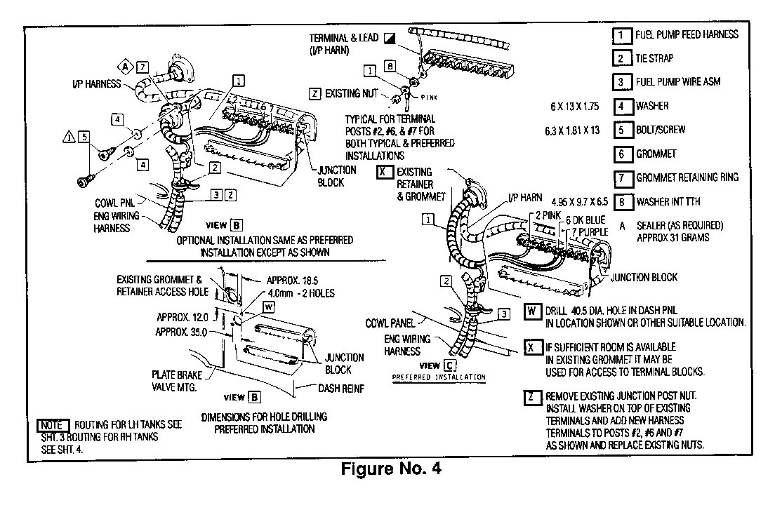
Preferred Installation (Figure 4, View C)
1.
a. Remove the grommet and retaining ring from the cowl panel where the instrument panel harness is routed. If there is room, route the fuel pump feed harness (1) through this hole. It may be necessary to cut the conduit away from the fuel pump feed harness so that it will fit with the IP harness and other harnesses passing through this hole. Only remove the conduit from the harness where it passes through the cowl.
Tape unprotected wires with electrical tape. Conduit must remain on the harness on either side of the cowl. Reseal cowl to prevent water leaks.
Optional Installation (Figure 4, View B)
b. If there is not enough room for the fuel pump harness (1) to route with the instrument panel harness and other harnesses, a new hole must be cut in the cowl panel. This hole is to the right of the fuse block just below the IP harness is routed in the engine compartment. After lifting the floor mat inside the cab, hold the retaining ring (7) as a template below existing harness hole and centre punch the new harness hole. Drill out this hole, using a 40mm hole saw in the cowl cover panel from inside the engine compartment.
NOTICE: Care should be used when drilling this hole so that other vehicle components or harnesses are not damaged.
Using the retaining ring (7) as a template, drill out two 4mm holes for attaching screws (5). Route the harness through this hole and install retaining ring and grommet (7). Then place sealant around this area to prevent water from entering cab. Attach retaining ring with screws (5) and washers (4).
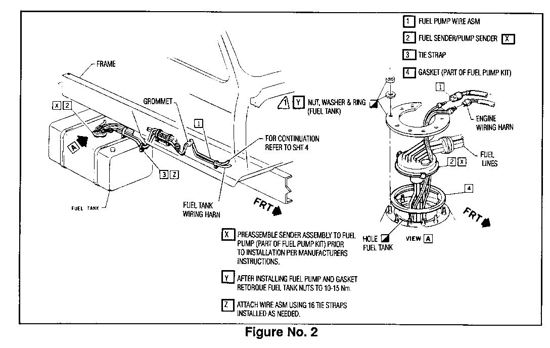
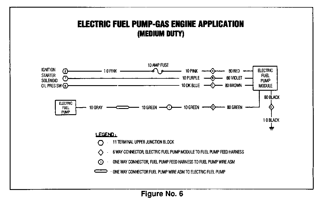
2. Install fuel pump module (2)(Figure 2) on fuse block. Connect module to fuel pump feel harness (1).
IMPORTANT: It may be necessary to cut away floor pad when installing fuel pump module.
3. Route fuel pump feed harness ring terminals to the upper electrical terminal block posts (Figure 4) as follows: Pink wire to post 2, dark blue wire to post 6, and purple wire to post 7. To connect wires, remove existing junction post nuts and install internal tooth lock washer (8) over existing terminals. Install new harness ring terminals and reinstall nuts.
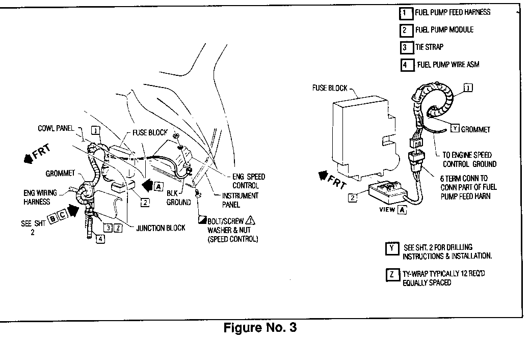
4. Route block ground wire with IP harness to engine speed control box (Figure 3) and connect the ring terminal to the box mounting screw beneath mounting bar. Torque to 1.6-3.4 Nm. Clean paint from area to insure a good electrical ground.
C. Fuel Pump Wire Installation ------------------------------ 1. Connect fuel pump wire assembly (4)(Figure 3) to the fuel pump feed harness (1) and using the tie strap (3) secure connector in place.
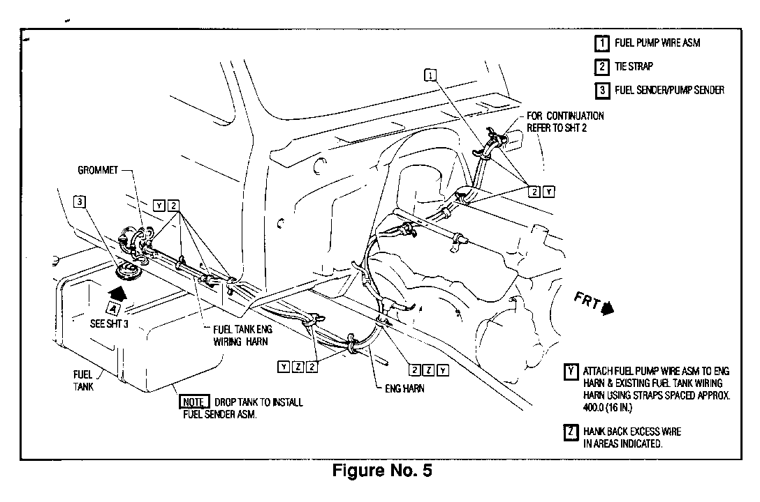
2. Route the pump feed wire assembly to the fuel tank sender/ pump. For a left hand tank, route feed wire with the rear lamp harness (Figure 1) and tie strap in place with four (4) tie straps (3) spaced approximately 400 Nm (16 inches) apart. For a right hand fuel tank (Figure 5), route feed wire with the engine harness. Tie back any excess feed wire to the engine or tail lamp harness and tie strap.
D. Reinstallation of Fuel Tank ------------------------------ 1. Reconnect the fuel lines to the new fuel sender/pump assembly (2)(Figures 1 and 2).
2. Reinstall the nuts on the fuel tank support straps stud bolts. Torque to 40-57 Nm.
E. Final Check
1. Reinstall tank drain plug.
2. Reconnect negative battery cable.
3. Refill the fuel tank with fuel and operate pump.
IMPORTANT: To check if in-tank pump is operating, listen for buzzing sound in the fuel tank when the key is turned to the "run" position.
Parts Information
Parts are currently available from CANSPO.
For 60 Gallon Fuel Tank (INNW)
Part Number Description Quantity ----------- ----------- -------- 15625398 Vapor Kit (electrical 1 components) 25093940 Sender Assembly 1 25115955 Fuel Pump 1
For 35 Gallon (PZQ/IPZ or 50 Gallon (IPZR) Fuel Tank ---------------------------------------------------- 15625397 Vapor Kit (electrical 1 components) 25094473 Sender Assembly 1 25115955 Fuel Pump 1
General Motors bulletins are intended for use by professional technicians, not a "do-it-yourselfer". They are written to inform those technicians of conditions that may occur on some vehicles, or to provide information that could assist in the proper service of a vehicle. Properly trained technicians have the equipment, tools, safety instructions and know-how to do a job properly and safely. If a condition is described, do not assume that the bulletin applies to your vehicle, or that your vehicle will have that condition. See a General Motors dealer servicing your brand of General Motors vehicle for information on whether your vehicle may benefit from the information.
