IMPROVED HEATER PERFORMANCE FOR SUB-ZERO TEMPERATURES

SUBJECT: IMPROVING HEATER PERFORMANCE ON 8.2L ENGINE POWERED SCHOOL BUSES AT SUB-ZERO TEMPERATURES
VEHICLES AFFECTED: 1981-1988 B6P042 SCHOOL BUS MODELS
Since the introduction of direct injection diesel engines in school bus applications, comments have been received from operators of the reduced ability of the diesel engine to provide hot enough coolant to maintain comfortable temperatures in cold ambient conditions. Most comments fall into two general categories:
- Unable to warm the bus properly after initial cold start
- Unable to maintain warm enough temperatures during pickup cycle (Stop and go low speed)
Heater performance specifically of 8.2L powered buses is often negatively compared to that of gasoline or other less fuel efficient indirect injection diesel powered buses.
From our experience the following factors may limit school bus heater performance:
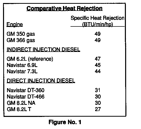
1. Lower heat rejection from the 8.2L. A fuel efficient, direct injection diesel engine such as the 8.2L rejects significantly less heat to the cooling system than gasoline or indirect diesel engines used for the same service. Figure 1 is a comparison of engines that illustrates this.
2. Chassis/Body Issues. Such differences at the source of heat tend to be amplified by conditions in the bus heater system that inhibit delivery of heat to the cab. Conditions that have been found are:
o Improperly routed heater hoses.
o No boost pump in the heater circuit when required.
o Improperly installed boost pumps.
o Low and aerated coolant.
o Inappropriate bus specification-vehicle not winterized:
- No radiator shutters.
- Heater lines not insulated.
- Windows and floors not properly insulated.
- Low output/highly restricted heater cores.
o Maintenance of cooling system and heater cores.
In 1986, Detroit Diesel distributed a bulletin detailing the steps that should be taken to optimize heat delivery from the engine. This bulletin included discussions on cold weather operation, cooling/heating system maintenance, heater system arrangements and proper vehicle specification. Another bulletin was distributed in 1987 that detailed series and parallel plumbing systems.
The purpose of this bulletin is to recap and revise the information provided in the 1986 and 1987 bulletins. The revisions consist of recommendations that derived from extensive testing conducted by CPC (Chevrolet, Pontiac and GM of Canada) and GM Truck and Bus personnel.
The following discussion will centre around the factors that impact school bus heat conditions and recommendations to optimize each one. Those factors are:
1. Low Heat Rejection Fuel Efficient Engine
2. Thermostats and Deaeration Lines
3. Heater Hose Routing
4. Booster Pump
5. Coolant System
6. Vehicle Cold Weather Package
LOW HEAT REJECTION FUEL EFFICIENT ENGINE
The 8.2L engine is a direct injection, fuel efficient, low heat rejection engine by design. The coolant takes longer to reach an operating temperature of 176 - 201 degrees Fahrenheit (30 - 94 degrees Celsius) . This situation can be improved if, after start up when oil pressure is obtained, the engine is run at a high idle (1500-2000 RPM for 5 to 6 minutes.
THERMOSTATS AND DEAERATION LINES
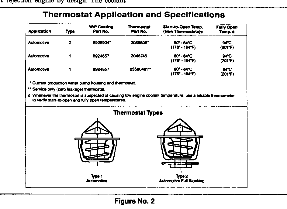
THERMOSTATS - Some early built engines used a non-blocking, notched thermostat that allowed some coolant flow through the radiator for deaeration during closed stat operation. Later, the notch was removed from the thermostat (no leak thermostats).
Engines built after Serial Number 8G-118764 use a full blocking, "no leak" thermostat.
It is important to note that the water bypass characteristics (non-blocking vs. full blocking) be matched to the correct water pump. The non-blocking thermostat is P/N 23500481 and must not be used in place of the current production thermostat (full blocking). Doing this reduces coolant flow through the radiator and could result in engine overheat in warmer weather. For reference, refer to Figure 2.
The Detroit Diesel "Power Pipeline,, bulletin mentions a "zero leak" thermostat that utilizes a rubber seal to eliminate closed stat coolant radiator flow and shorten warmup time. However, testing has shown no measurable difference between the "zero leak" and production "no leak" thermostats.
DEAERATION LINE - The deaeration line that is required on the engine is another source of heat loss during engine warm up. By reducing the deaeration flow, warmup time is improved. Our recommendation is to use a minimum deaeration line size of .135" (1/8") I.D.
HEATER HOSE ROUTING
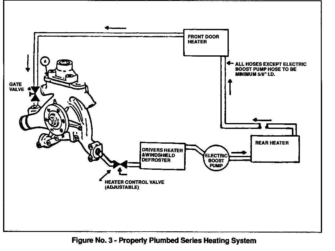
Correct heater hose routing/plumbing is another important factor to maximize heater output when operating a vehicle in cold climates. Heater hoses should be routed to maximize coolant flow and to minimize heat rejection outside the vehicle. Figure 3 is an example of a correctly plumbed series arrangement. The one major difference between the 1986 and 87 bulletins is that the heater 'in" line is plumbed into the pressure outlet of the water pump instead of from top of the thermostat housing. This improves coolant flow by 25% which also improves heater output.
Note: Coolant flow should be a minimum of 4 GPM at idle.
Earlier and most existing buses utilize series plumbing, however, some newer models will use a parallel system which has proved to be a more efficient system. A comparison of these two systems is covered in the following paragraphs:
Series Plumbing (Figure 3) is effective when "V" cell radiator type heat exchange cores are used in the heater units. These cores have moderate pressure drop associated with them, but require the water in to be plumbed into the lower port and the water out to be from the top, causing a "flooding" of the heat exchange core. Otherwise there should be some means to bleed entrapped air from the core.
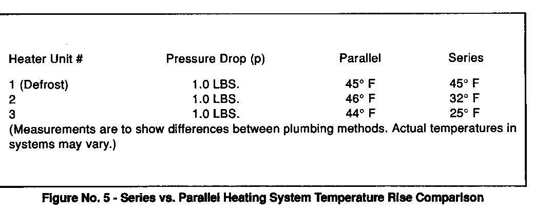
In a series system, hot water goes through the first heater, then on to the next heater and so on. Each core in this chain adds some restriction, resulting in decreased coolant flow (Flow should be minimum of 4 GPM at idle). Water temperature is also reduced by each heater, so the last heater may get water that is too cool to be effective at lower RPM. The same capacity heater can deliver more heat if it is the first in the series, rather than second or third.
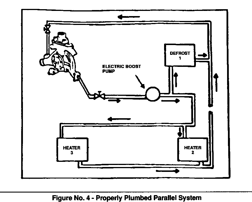
Parallel Plumbing (Figure 4) is effective only when aluminum/copper tube and fin type heat exchanger coils are used in the heater units. These coils have moderate pressure drops associated with them. When plumbed in parallel, total system pressure drop is not the sum of all the coils, as with the cores in series plumbing.
All coils used in a parallel-plumbed system must be designed with circuitry that will provide a balance in the system. This may be accomplished within the coil design or with the use of properly placed orifices which can restrict flow at various points and force equal amounts of coolant to other parts of the system.
In a parallel system, the hot water is divided so that part of it flows directly to each heater. The outlets from all of the heaters join to a single return line. Each heater in the parallel system receives the hottest water available. Adding more coils to a parallel system provides extra paths for the hot water and allows the same pump to deliver a greater total water flow because of the minimal pressure drop through the total system. Figure 5 illustrates how a professionally designed, well balanced parallel heating system can deliver even heating.
BOOSTER PUMP
To maintain a coolant f low through the heater system of 4 GPM at idle, a booster pump is required. The pump should have a capacity of 9-12 gallons per minute and a heavy duty permanent magnet type 12 volts D.C. motor with minimal amperage draw. The pump should be compatible with permanent ethylene glycol antifreeze.
In a series plumbed system, the pump should be installed between the first and second heater core (Reference Figure 3) and in a parallel system between the engine and the "in" side of the heater system (Reference Figure 4).
COOLANT SYSTEM
Another vital element of the heater system is the proper fill of the cooling system. The coolant must be free from air and contaminants such as oil. The heaters will not properly transfer heat if the coolant is aerated. Aerated coolant can also cause the engine water pump and booster pump to cavitate, resulting in no flow through the heater system. This can also produce an air lock in the heater cores which stops flow.
It is very important to completely fill the cooling system and keep it deaerated. The following will help in filling and deaerating the system:
NOTICE: DURING THE FILLING AND BLEEDING PROCESS IT WILL BE NECESSARY TO REMOVE THE RADIATOR CAP AND REFILL THE COOLING SYSTEM SEVERAL TIMES TO ENSURE THAT ENOUGH COOLANT IS AVAILABLE TO REPLACE THE AIR PURGED AND COOLANT LOST WHEN BLEEDING.
CAUTION:
USE EXTREME CARE WHEN REMOVING A RADIATOR PRESSURE-CONTROL CAP FROM AN ENGINE. THE SUDDEN RELEASE OF PRESSURE FROM A HEATED COOLING SYSTEM CAN RESULT IN A LOSS OF COOLANT AND POSSIBLE PERSONAL INJURY (SCALDING) FROM THE HOT LIQUID.
1. Fill the cooling system completely, including the surge and recovery tank. Install radiator cap.
2. With heater valve closed, operate engine at high idle (1500-2000 RPM) for 3-4 minutes. This allows the engine to deaerate.
3. Remove radiator cap (See Caution) and top off cooling system. Leave radiator cap off.
4. Operate engine at high idle (2000-2500 RPM). Open heater valve and turn booster pump on. Run engine several minutes to bleed air from system. It may be necessary to refill radiator and/or surge tank several times when bleeding air from coolings system.
5. If the heaters are equipped with bleed valves, open valves until air is purged.
6. Top off cooling system, replace radiator cap and operate engine at high idle (2000-2500 RPM) until thermostats open.
Thermostats have opened when the upper radiator hose becomes hot (normally between 176 and 184 degrees Fahrenheit (80 - 84 degrees Celisus).
Further purging of air will be accomplished through the coolant recovery system. As the engine cools down and a vacuum is formed in the cooling system, coolant will be drawn from the recovery tank to displace any air in the cooling system. The coolant level must be maintained above the "cold full" line in the recovery tank at all times to ensure that the entire cooling system remains free of air. The recovery system should have a functional capacity of one gallon minimum.
VEHICLE COLD WEATHER PACKAGE
A bus that has not been properly winterized when operating in sub-zero climates may not be able to maintain a comfortable heat level for its occupants. There are certain items that should be specified to winterize the vehicle for sub-zero operation This list includes:
1. Radiator shutters
2. Insulated windows and floors
3. High output, low restriction heater cores
4. Inside/insulated plumbing
It is our hope that the information in this article will help in troubleshooting comments of "low heat" or "no heat" in 8.2L powered school buses. We especially hope this information is helpful to dealers, municipalities and school districts when specifying a bus for use in colder climates.
General Motors bulletins are intended for use by professional technicians, not a "do-it-yourselfer". They are written to inform those technicians of conditions that may occur on some vehicles, or to provide information that could assist in the proper service of a vehicle. Properly trained technicians have the equipment, tools, safety instructions and know-how to do a job properly and safely. If a condition is described, do not assume that the bulletin applies to your vehicle, or that your vehicle will have that condition. See a General Motors dealer servicing your brand of General Motors vehicle for information on whether your vehicle may benefit from the information.
