FALSE AUX. BRAKE WARNING LIGHT REPLACE MODULE/BRAKE SWITCH

SUBJECT: FALSE AUXILIARY BRAKE WARNING LIGHT
MODELS: 1990 C5H, C6H, C7H TOPKICK/KODIAK MEDIUM DUTY TRUCKS WITH HYDRAULiC BRAKES (JE3)
Some 1990 TopKick/Kodiak medium duty trucks, equipped with hydraulic brakes, may have a condition in which the auxiliary brake warning light illu- minates and sounds an alarm with no apparent cause. To address this condition a revised brake pedal switch and a revised alarm/brake booster module have been released.
! Important ------------
The new brake module and brake switch will not solve all customer complaints. It is essential that the new module and switch be used only after performing the following tests.
- Check the brake pedal switch to see that it is adjusted properly. Adjustment procedures may be found later in this bulletin.
- Check the power steering fluid level, and make sure the system is properly bled.
Verify the conditions under which the auxiliary brake warning light illuminates:
- If the warning comes on along with the primary brake warning light, solve the primary light symptom first. The primary warning light may be causing the auxiliary warning to light up.
- if the warning comes on as a result of pushing the brake pedal to just turn on the rear stop lamps, but not pushing far enough to activate the booster part of the pedal switch, replace the brake pedal switch. A typical customer complaint for this symptom would be that the auxiliary warning light comes on when the truck is slowly approaching a stop, or the customer is preparing to stop.
- If the warning comes on while turning the steering wheel to the stops and applying the brake, or if the warning comes on during vehicle start, the electrical boost system needs to be diagnosed. Diagnose the electrical system in accordance with the "Electrical Diagrams And Diagnosis Manual" for 1990 C5H, C6H, C7H models (stock number X-9041). The procedures are found in the "Alarm and Brake Booster Modules" section on page 130. The manual is arranged so that all systems are checked except the module, and the module is replaced by default. Before replacing a module, the problem should be verified once more to ensure that there was not a problem with a connector that was eliminated by disconnecting and reconnecting it.
PARTS INFORMATION:
Revised Module:
New Part # Application Option Code ---------- ------------ ----------- 15660916 diesel engin with LXO & KPJ automatic shut down --------- -------------------- ----------- 15660911 diesel engine without LXO shut down --------- --------------------- ----------- 15660912 gas engines LRO/LSO
The part number is printed on a colored piece of tape on the connector. These new parts will also have a different alarm tone frequency from the earlier parts.
Revised Brake Switch:
New Part # Application --------- ---------------------------------- 15676475 all 1990 TopKick/Kodiaks with hydraulic brakes
The new switch will have a gray adjustment arm for easy identification. The old switch will have a black adjustment arm. Parts are currently available through GMSPO.
SERVICE PROCEDURES:
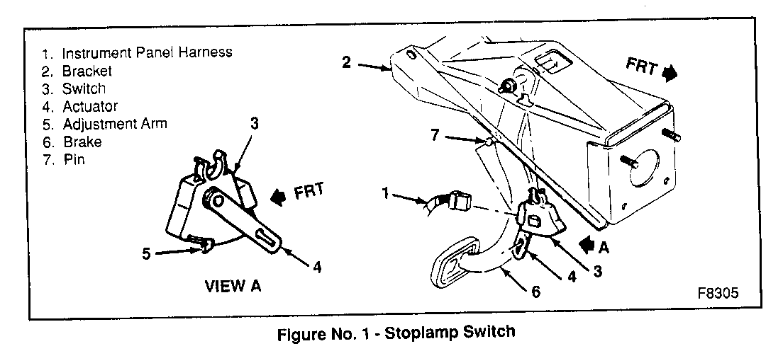
Brake Switch Adjustment (see Figure 1):
1. Depress the brake pedal as far as it will go.
2. Pull the adjustment arm rearward (towards the driver) as far as it will go.
3. Release the brake pedal and allow it to return to its normal position. Lightly pull up on the pedal to ensure that the pedal is fully returned.
4. Verify that the stop lamps illuminate properly.
Brake Switch Replacement Procedure (see Figure 1):
1. Pull down on the brake switch to remove it.
2. Disconnect the harness from the brake switch.
3. Connect the harness to the new switch.
4. Align the pin on the brake pedal with the slot in the adjustment arm of the new switch, and align the tab on the switch case with the slot on the bracket.
5. Push the switch up until the clip on top of the switch clips around the brake pedal pivot rod.
6. Adjust the switch as detailed above.
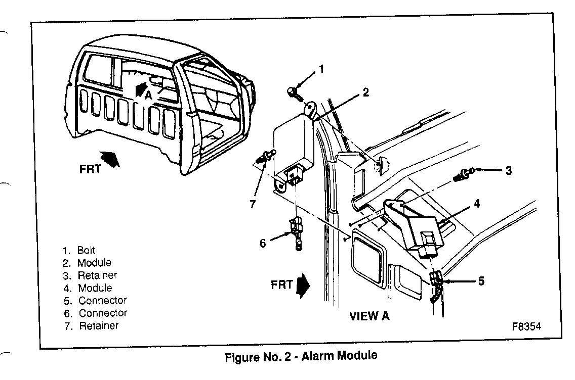
Module Replacement Procedure (see Figure 2):
1. Remove the left front speaker grille and the speaker
2. Disconnect the connector (6) to the module (2).
3. Remove the plastic rivet (7) at the bottom of the module from under the instrument panel.
4. Unscrew the 10mm hex head screw (1) at the top of the module.
5. Remove the module through the speaker opening.
6. Replace the module and the 10mm hex screw through the speaker opening.
7. Install the plastic rivet from under the instrument panel to the bottom of the module.
8. Connect the electrical connection to the module.
9. Install the speaker and the speaker grille.
WARRANTY INFORMATION
For vehicles repaired under warranty use:
Labor Description Operation --------- --------------- N2440 Stop lamp switch replace --------- ------------------------------ N1890 Alarm, multi-function, replace


General Motors bulletins are intended for use by professional technicians, not a "do-it-yourselfer". They are written to inform those technicians of conditions that may occur on some vehicles, or to provide information that could assist in the proper service of a vehicle. Properly trained technicians have the equipment, tools, safety instructions and know-how to do a job properly and safely. If a condition is described, do not assume that the bulletin applies to your vehicle, or that your vehicle will have that condition. See a General Motors dealer servicing your brand of General Motors vehicle for information on whether your vehicle may benefit from the information.
