SERVICE MANUAL UPDATE SEC. 7C CLUTCH ADJUSTMENT PROCEDURE

SUBJECT: INTERNAL SPICER CLUTCH ADJUSTMENTS (SERVICE MANUAL UPDATE SECTION 7C-CLUTCH)
MODELS: 1990-91 W7 HEAVY SERIES FORWARD/TILTMASTER TRUCKS EQUIPPED WITH 8.0L ISUZU ENGINES. C7D MODELS EQUIPPED WITH 3208 CATERPILLAR ENGINES. AND C7H TOPKICK/KODIAKS EQUIPPED WITH 3116 ENGINES AND SPICER DUAL PLATE 14" STAMPED ANGLE-SPRING CLUTCHES WITHOUT CLUTCH BRAKES
Improper clutch adjustments may cause slippage, hard shift, clutch drag and poor/no release conditions.
Below is information regarding Spicer dual plate clutch internal Free Play adjustments. This information supplements section 7C-Clutch of the following Service Manuals:
- Forward/Tiltmaster W5, W6 and W7 Series Trucks (X-8966)
- 1990 Medium Truck C5D, C6D, C7D, B6p, S7T, P4T, P6T Supplement (X-9034)
- 1990 Medium Truck C5H, C6H, C7H Models (X-9033)
CLUTCH ADJUSTMENT PROCEDURES FOR MANUALLY ADJUSTED CLUTCHES WITHOUT CLUTCHBRAKES ------------------------------------------ 1. Block the vehicle to prevent movement and set the park brake.
2. Remove the release bearing inspection cover located on the clutch housing.
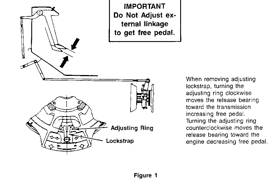
3. Remove the lockstrap (Figure 1).
4. NOTE: CORRECT POSITIONING OF THE RELEASE BEARING IS 3/4". CHECK THE MEASUREMENT WITH THE PEDAL IN THE "UP" POSITION.
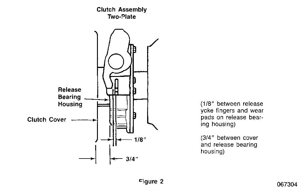
To position the release bearing, with the pedal depressed, turn the adjusting ring to obtain approximately 3/4" between the cover and release bearing housing (Figure 2).
Turning the adjusting ring clockwise moves the release bearing toward the transmission and increases free pedal. Turning the adjusting ring counterclockwise moves the release bearing toward the engine and decreases free pedal.
5. Only on Topkick/Kodiak trucks, check the clutch pedal bump stop bracket for deformation. This bracket is located in the cab. If the bracket is bent beyond its 90 degree original bend, the clutch pedal height will increase depending on the severity of the bend. A high clutch pedal position may give an incorrect free travel setting and cause overtravel of the clutch linkage.
If the bracket is bent, replace with new part number 15671005.
6. Proper free travel at the clutch pedal should be approximately 1-1/2'. If adjustment is required, turning the adjusting ring clockwise moves the release bearing toward the transmission increasing free travel. Turning the adjusting ring counter-clockwise moves the release bearing toward the engine decreasing free travel (Figure 1).
NOTE: FOR MANUAL ADJUSTED CLUTCHES, DO NOT ADJUST EXTERNAL LINKAGE TO GET FREE TRAVEL.
NOTE: VEHICLES EQUIPPED WITH HYDRAULIC LINKAGE - REFER TO THE MANUFACTURER'S SPECIFICATIONS FOR PROPER ADJUSTMENT OF SYSTEM. VERIFY 1/2' MINIMUM RELEASE TRAVEL BETWEEN THE RELEASE BEARING AND TRANSMISSION BEARING CAP.
7. Reinstall the lockstrap. Tighten both bolts to 22-48 N.m (30-35 Lbs Ft) torque.
8. Lubricate the clutch after adjustments have been made. Use P/N 1051344.
9. Reinstall inspection cover.
10. Remove wheel blocks.
11. Test drive to verify proper operation.
CLUTCH ADJUSTMENT PROCEDURES FOR SELF-ADJUSTING CLUTCHES WITHOUT CLUTCH BRAKES ---------------------------------------------------------------- 1. Block wheels to prevent movement and set park brake.
2. Remove the inspection cover.
3. NOTE: CORRECT POSITIONING OF THE RELEASE BEARING IS 3/4". CHECK THE MEASUREMENT WITH THE PEDAL IN THE "UP" POSITION.
To position the release bearing, with the pedal depressed, turn the adjusting ring to obtain approximately 3/4" between the cover and release bearing housing (Figure 2). Turning the adjusting ring clockwise moves the release bearing toward the transmission and increases free pedal. Turning the adjusting ring counter- clockwise moves the release bearing toward the engine and decreases free pedal.
4. Only Topkick/Kodiak trucks, check the clutch pedal bump stop bracket for deformation. If the bracket is bent beyond its 90 degree original bend, the clutch pedal height will increase depending on the severity of the bend. A high clutch pedal position may give an incorrect free travel setting and cause over-travel of the clutch linkage.
If the bracket is bent, replace with new part number 15671005.
5. Proper free travel should be 1/8" between the release yoke fingers and wear pads on the release bearing housing. If adjustment is required, adjust the external linkage by shortening or lengthening to obtain the desired 1/8" dimension. This 1/8" will provide approximately 1-1/2" free travel at the clutch pedal (Figure 2). Tighten all locknuts.
NOTE: VEHICLES EQUIPPED WITH HYDRAULIC LINKAGE - REFER TO THE MANUFACTURER'S SPECIFICATIONS FOR PROPER ADJUSTMENT OF THE SYSTEM. VERIFY 1/2" MINIMUM RELEASE TRAVEL BETWEEN THE RELEASE BEARING AND TRANSMISSION BEARING CAR
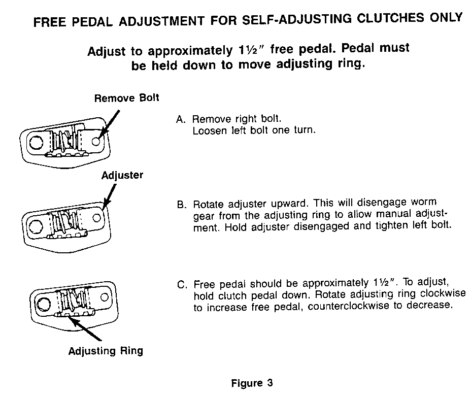
6. Proper free pedal adjustment should be approximately 1-1/2". If adjustment is required to obtain proper free pedal, perform the following steps.
- Remove the right bolt from the adjuster.
- Loosen the left bolt one turn.
- Rotate the adjuster upward. This will disengage the worm gear from the adjusting ring to allow manual adjustment.
- Hold the adjuster disengaged and tighten the left bolt to 22-48 Nm (30 - 35 Lbs. Ft.).
- Hold the clutch pedal down and rotate the adjusting ring clockwise to increase free pedal or counterclockwise to decrease it.
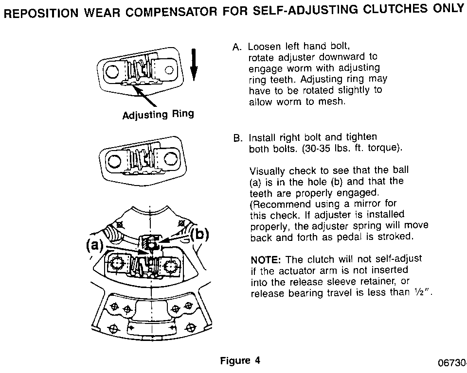
7. To reposition the wear compensator perform the following steps: (Figure 4).
- Loosen the left hand bolt on the adjuster.
- Rotate the adjuster downward to engage the worm with the adjusting ring teeth. The adjusting ring may have to be rotated slightly to allow the worm to mesh.
- Install the right bolt on the adjuster. Tighten both the right and left bolts to 22-48 Nm (30-35 Lbs Ft) torque.
- Visually check to see if the actuator arm (a) is inserted into the release sleeve retainer (b). The ball should be in the hole and the teeth properly engaged. (A mirror is recommended for this check.) If the adjuster is installed properly, the adjuster spring will move back and forth as the pedal is stroked.
NOTE: THE CLUTCH WILL NOT SELF-ADJUST IF THE ACTUATOR ARM IS NOT INSERTED INTO THE RELEASE SLEEVE RETAINER, OR IF THE RELEASE BEARING TRAVEL IS LESS THAN 1/2".
8. Lubricate the clutch after adjustments have been made. Use GM P/N 1051344.
9. Reinstall the inspection cover.
10. Remove the blocks.
11. Test drive to verify proper operation.
SERVICE PARTS INFORMATION
Part Number Description ----------- ----------------- 15671005 Bump Stop Bracket 1051344 Clutch Lubricant
FREE PEDAL ADJUSTMENT (Internal Clutch Adjustment) FOR MANUAL ADJUSTED CLUTCHES ONLY ---------------------------------------------------- Adjust to approximately 11/2' free pedal. Pedal must held down to move adjusting ring.
IMPORTANT Do Not Adjust external linkage to get free pedal.
When removing adjusting lockstrap, turning the adjusting ring clockwise moves the release bearing toward the transmission increasing free pedal. Turning the adjusting ring counterclockwise moves the release bearing toward the engine decreasing free pedal.
(1/8" between release yoke fingers and wear pads on release bearing housing)
(3/4" between cover and release bearing housing)
FREE PEDAL ADJUSTMENT FOR SELF-ADJUSTING CLUTCHES ONLY (Figure 3)
Adjust to approximately 1 1/2" free pedal. Pedal must be held down to move adjusting ring.
A. Remove right bolt. Loosen left bolt one turn.
B. Rotate adjuster upward. This will disengage worm gear from the adjusting ring to allow manual adjustment. Hold adjuster disengaged and tighten left bolt.
C. Free pedal should be approximately 1 1/2". To adjust, hold clutch pedal down. Rotate adjusting ring clockwise to increase free pedal, counterclockwise to decrease.
REPOSITION WEAR COMPENSATOR FOR SELF-ADJUSTING CLUTCHES ONLY (Figure 4)
A. Loosen left hand bolt, rotate adjuster downward to engage worm with adjusting ring teeth. Adjusting ring may have to be rotated slightly to allow worm to mesh.
B. Install right bolt and tighten both bolts. (30-35 lbs. ft. torque).
Visually check to see that the ball (a) is in the hole (b) and that the teeth are properly engaged. (Recommend using a mirror for this check. if adjuster is installed properly, the adjuster spring will move back and forth as pedal is stroked.
NOTE: The clutch will not self-adjust if the actuator arm is not inserted into the release sleeve retainer, or release bearing travel is less than 1/2".


General Motors bulletins are intended for use by professional technicians, not a "do-it-yourselfer". They are written to inform those technicians of conditions that may occur on some vehicles, or to provide information that could assist in the proper service of a vehicle. Properly trained technicians have the equipment, tools, safety instructions and know-how to do a job properly and safely. If a condition is described, do not assume that the bulletin applies to your vehicle, or that your vehicle will have that condition. See a General Motors dealer servicing your brand of General Motors vehicle for information on whether your vehicle may benefit from the information.
