CHECK GAUGES LIGHT COMES ON & ALARM ACTIVATES

SUBJECT: CHECK GAGES LIGHT COMES ON AND ALARM ACTIVATES (REPLACE TEMPERATURE CIRCUIT BOARD OR INSTRUMENT CLUSTER)
MODELS: 1990-93 TOPKICK/KODIAK W/LXO, LSO, LRO
CONDITION
Some of the above subject vehicle's "check gages" lamp and alarm may react as if the engine is in an overheat condition. A flickering check gages lamp and/or a chirping sound is typical of this condition. This condition usually appears when the engine is warm.
CAUSE
It has been determined the "check gages" circuit board can send a false overheat condition signal and cause the above concern.
CORRECTION
Replace the "check gages" circuit board or EXCHANGE the instrument cluster through your Delco Authorized Service Center (Refer to Truck Bulletin 90-8C-10, Corp #968301R).
Note: The cluster exchange program is available and is encouraged for situations in which downtime is not a factor or when it is not clear which component is defective.
SERVICE PROCEDURE
Removal of Cluster
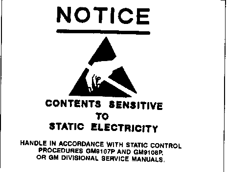
Notice: Many solid state electrical components can be damaged by Electrostatic Discharge (ESD). Some will display a symbol (Figure 1) but many will not, Be sure to follow ESD Sensitive procedures listed in section 8C of the Service Manual when performing this procedure. Failure to do so could result in damage to the instrument cluster components.
INSTRUMENT CLUSTER R AND R OR REPLACEMENT
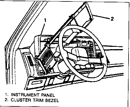
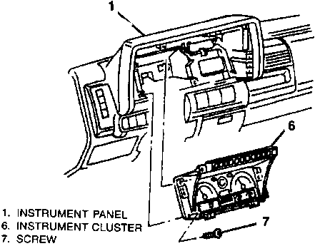
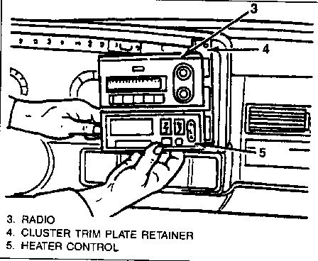
Remove or Disconnect (Figures 2, 3, and 4)
1. Negative battery cable.
2. Drain air tanks. (Air brake models only)
3. Six (6) screws retaining the instrument cluster trim plate bezel (Figure 2, Item 2).
4. Trim plate bezel. Rotate bezel upward and to the left as shown in Figure 2 to access instrument cluster retaining screws(Figure 3, Item 7).
5. Six (6) screws retaining the cluster trim plate retainer.
6. Cluster trim plate retainer (Figure 4, Item 4) with radio (Figure 4, Item 3) and heater control (Figure 4, Item 5).
7. Four (4) screws (Figure 3, Item 7) retaining the instrument cluster.
8. For Air Brake Models only: disconnect the air lines from the back of the air gauge. Note where the air lines are connected.
9. Instrument cluster (Figure 3, Item 6).
Install or Connect (Figures 2, 3, and 4)
1. Instrument cluster (Figure 3, Item 6).
2. Air lines to back of air gage (Air brake models only).
3. Four (4) instrument cluster retaining screws (Figure 3, Item 7).
4. Cluster trim plate retainer (Figure 4, Item 4) with radio(Figure 4, Item 3) and heater control (Figure 4, Item 5). Position the assembly in the instrument panel (Figure 3, Item 1) and install the instrument cluster retaining screws (Figure 3, Item 7).
5. Six (6) cluster trim plate retainer screws.
6. Negative battery cable.
CIRCUIT BOARD REMOVAL
Remove or Disconnect
1. Follow instrument cluster R and R or replacement procedure, remove or disconnect section, Items 1-9.
2. Place cluster assembly on bench under the conditions described in the ESD section of this bulletin!
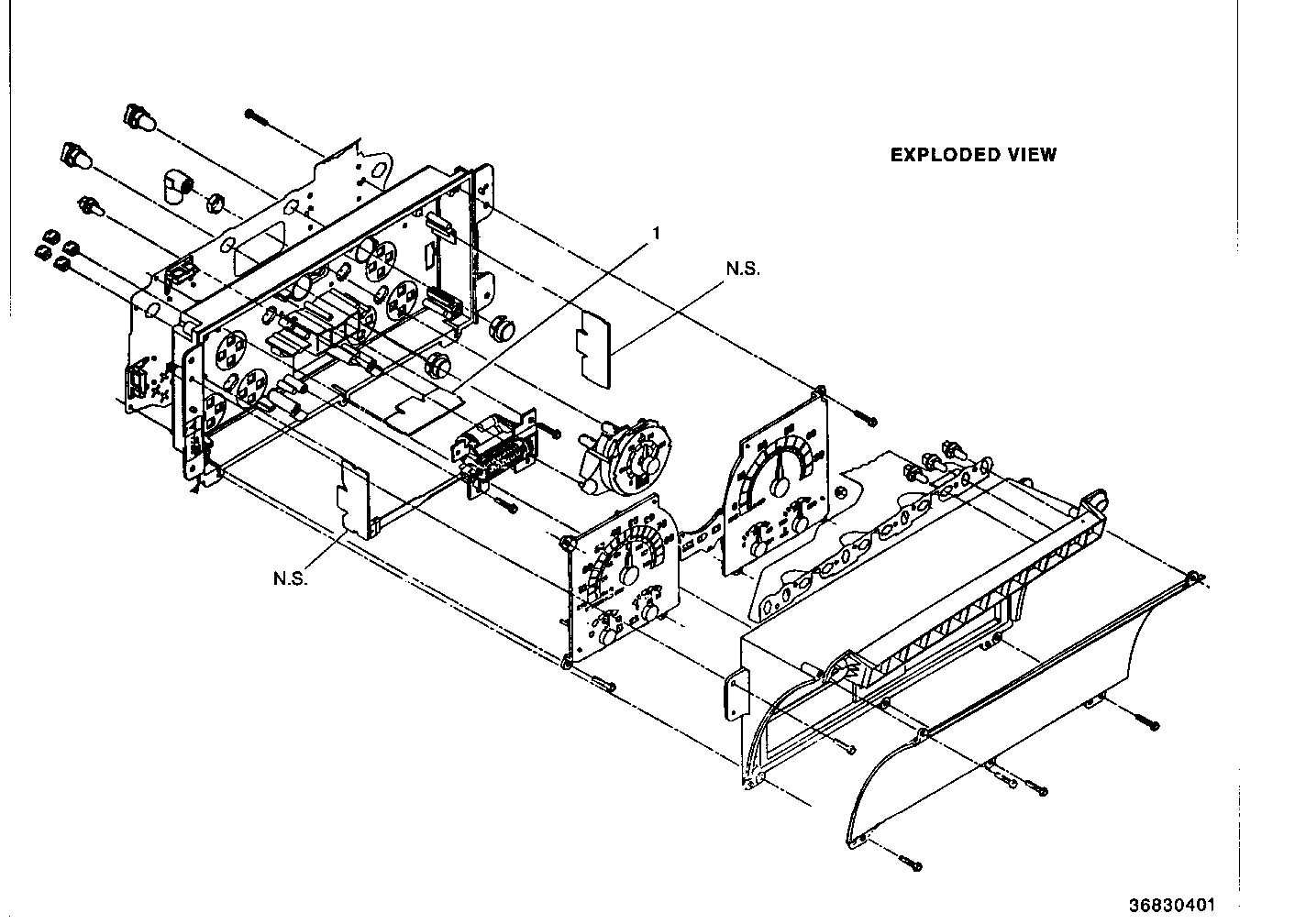
3. Remove five (5) screws around the perimeter of the lens.
4. Carefully lift off the lens and retainer as one (1) piece, being careful not to damage the flex circuit (you do not need to remove the flex circuit to remove the lens and retainer).
Note: The flex circuit is not serviced separately.
5. Three screws from the left hand gage cluster.
6. Lift the gage cluster out of the case.
7. Locate the temperature gage circuit board, located in the upper left center area of the cluster case (Figure 5, Item 1).
Note: Only the "check gages" circuit boards are available through GMSPO,
8. Unplug the harness from the circuit board.
9. Carefully lift the circuit board out of the case.
CIRCUIT BOARD REPLACEMENT
Install or Connect
1. Circuit board.
2. Harness.
3. Gage cluster into cluster case.
4. Three (3) screws into gage cluster.
5. Lens and retainer as one piece onto the cluster case.
6. Five (5) screws around the perimeter of the lens.
7. Follow instrument cluster R and R or replacement procedure, install or connect, items 1-6.
SERVICE PARTS INFORMATION
P/N Description --- ----------- 25073016 "Check Gages" circuit board, Diesel 25073012 "Check Gages" circuit board, Gasoline
Parts are currently available from GMSPO.
WARRANTY INFORMATION
For vehicles repaired under warranty, use:
Labor Op Description Labor Time -------- ----------- ---------- N4775 Gage, Replace See Applicable Labor Time Guide
General Motors bulletins are intended for use by professional technicians, not a "do-it-yourselfer". They are written to inform those technicians of conditions that may occur on some vehicles, or to provide information that could assist in the proper service of a vehicle. Properly trained technicians have the equipment, tools, safety instructions and know-how to do a job properly and safely. If a condition is described, do not assume that the bulletin applies to your vehicle, or that your vehicle will have that condition. See a General Motors dealer servicing your brand of General Motors vehicle for information on whether your vehicle may benefit from the information.
