SERVICEABILITY OF I/P CLUSTER GAUGES (INFORMATIONAL)

SUBJECT: SERVICEABILITY OF INSTRUMENT CLUSTER GAUGES (INFORMATIONAL)
MODELS: 1990-1992 5H, 6H, 7H TOPKICK/KODIAK
THIS BULLETIN CANCELS AND REPLACES GMC TRUCK BULLETIN-92-8C-53, PUBLISHED IN FEBRUARY 1992. IT WAS REVISED TO CORRECT THE PART NUMBERS AND DESCRIPTIONS OF SOME OF THE INSTRUMENT CLUSTERS. ALL COPIES OF 92-8C-53 SHOULD BE DISCARDED.
As part of our commitment to increase truck UPTIME, GMC TRUCK is pleased to announce the availability of replacement components within the instrument cluster on the TOPKICK/KODIAK.
Important
The cluster exchange program is still available and is encouraged for situations when it is not clear which component may be causing a concern.
SERVICE PROCEDURE:
REMOVAL OF CLUSTER
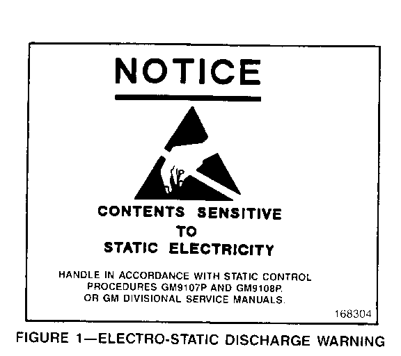
NOTICE: Many solid state electrical components can be damaged by Electrostatic Discharge (ESD). Some will display a symbol (Figure 1) but many will not. Be sure to follow ESD Sensitive procedures listed here and in section BC of the Service Manual when performing this procedure. Failure to do so could result in damage to the instrument cluster components.
1. Body movement produces an electrostatic charge. To discharge personal static electricity, touch a ground point (metal) on the vehicle. This should be done any time you:
- Slide across the seat - Sit down or get up - Do any walking
2. Do not touch exposed terminals on components with your fingers or tools. Remember, the connector that you are checking might be tied into a circuit which could be damaged by ESD.
3. When using a screwdriver or similar tool to disconnect a connector, never let the tool come in contact with or in between exposed terminals.
4. Never jump, ground, or use test equipment probes on any components or connectors unless specified in diagnosis. When using test equipment, always connect the ground lead first.
5. Do not remove the solid state component from its protective packaging until you are ready to install the part.
6. Always touch the solid state components package to a ground before opening. Solid state components can also be damaged if:
- They are bumped or dropped. - They are laid on any metal work benches or components that operate electrically, such as a TV, radio or oscilloscope.
7. The technician should wear a wrist strap and ground lead.
8. The instrument cluster should be transported to and from the vehicle in an ESD handling bag.
9. The work area should be covered by an approved, grounded floor mat. Painting the work area with conductive paint is not an approved alternative.
10. The work area must be free of static producing items such as styrofoam, plastic, carpet, etc.
Following these precautions will help protect sensitive electronic components.
INSTRUMENT CLUSTER R&R OR REPLACEMENT
1. Disconnect the negative battery cable.
2. Drain air tanks. (Air brake models only)
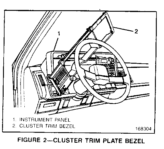
3. Remove the six (6) screws retaining the instrument cluster trim plate bezel (Figure 2, "2").
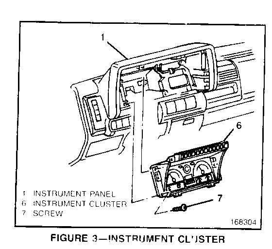
4. Remove the trim plate bezel (Figure 2, "2"). Rotate the bezel upward and to the left to access instrument cluster retaining screws (Figure 3, "7").
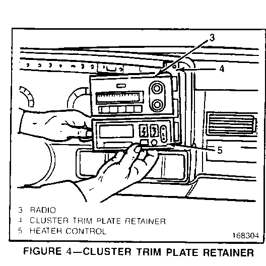
5. Remove the six (6) screws retaining the cluster trim plate retainer (Figure 4, "4").
6. Remove the cluster trim plate retainer (Figure 4, "4") with radio (Figure 4, "3") and heater controls (Figure 4, "5").
7. Remove the four (4) screws (Figure 3, "7") retaining the instrument cluster.
8. For air brake models only: disconnect the air lines from the back of the air gauge. Note where the lines are connected.
9. Remove the instrument cluster (Figure 3, "6").
10. Replace the defective component using the procedures described below.
11. Install the instrument cluster (Figure 3, "6").
12. On air brake models only: connect the air lines to the back of the air gauge.
Important
The dual air pressure gauge has two color coded needles. The yellow needle indicates the front service system air pressure and the green needle indicates the rear service system air pressure.
The air connection for the green needle is on the left side of the gauge (viewed from the rear of the gauge - see section 5B of the appropriate Service Manual). The line is routed through the bulkhead to an elbow on the dual application valve. The air connection for the yellow needle is on the right side of the gauge (viewed from the rear of the gauge). The line is routed through the bulkhead to a tee on the double check valve.
13. Install the four (4) instrument cluster retaining screws (Figure 3, "7").
14. Install the cluster trim plate retainer (Figure 4 "4") with the radio ( Figure 4, "3") and heater controls (Figure 4, "5"). Position the assembly on the instrument panel (Figure 3, "1") and install the six (6) retaining screws (Figure 3, "7").
15. Install the cluster trim plate bezel (Figure 2, "2") with the six (6) retaining screws.
16. Connect the negative battery cable.
AIR BRAKE GAUGE REMOVAL (Air Brake RPO JE4)
1. Remove the cluster assembly as described in the INSTRUMENT CLUSTER R&R PROCEDURE above. Place the cluster assembly on the bench under the conditions described in the ESD section of this bulletin!
2. Remove the two (2) 90 degree elbows from the air gauge nipples on the back of the cluster case.
3. Remove the two (2) hex nuts from the air gauge nipples on the back of the cluster case.
4. Remove the five (5) screws around the perimeter of the lens.
5. Carefully lift off the lens and retainer as one piece, being careful not to damage the flex circuit (you do not need to remove the flex circuit to remove the lens and retainer).
Important
The flex circuit is not serviced separately.
6. Remove the three (3) screws from each gauge cluster.
7. Lift both gauge clusters out of the cluster case.
8. Lift the air gauge out of the cluster case.
9. Install the new air gauge into the cluster case.
10. Install the two (2) hex nuts onto the gauge nipples on the back of the cluster case. Torque the nuts to 6.0 - 11.0 lbs. in. (0.7-1.2 N-m ).
11. Install the two (2) 90 degree elbows onto the gauge nipples on the back of the cluster case. Torque the nuts to 6.0 -11.0 lbs.in. (0.7-1.2 N-m ).
12. Insert the gauge clusters into the cluster case.
13. Install the three (3) screws into each gauge cluster. Torque the screws to 6-11 lbs. in. (0.7-1.2 N-m ).
14. Carefully insert the lens and retainer as one piece.
15. Install five (5) screws around the perimeter of the lens. Torque the screws to 6-11 lbs. in. (0.7-1.2 N-m ).
16. Install the instrument cluster as described in the INSTRUMENT CLUSTER R&R procedure above.
CLUSTER GAUGE REMOVAL AND INSTALLATION
1. Remove the instrument cluster as described in the INSTRUMENT CLUSTER R&R procedure above. Place the cluster assembly on a bench under the conditions described in the ESD section of this bulletin!
2. Remove the five (5) screws around the perimeter of the lens.
3. Carefully lift off the lens and retainer as one (1) piece, being careful not to damage the flex circuit (you do not need to remove the flex circuit to remove the lens and retainer).
Important
The flex circuit is not serviced separately.
4. Remove the three (3) screws from the gauge cluster.
5. Lift the gauge cluster out of the cluster case.
6. Set the new gauge cluster into the cluster case.
7. Install the three (3) screws into the gauge cluster.
8. Install the lens and retainer as one piece onto the cluster case.
9. Install the five (5) screws around the perimeter of the lens.
10. Install the instrument cluster as described in the INSTRUMENT CLUSTER R&R procedure above.
ODOMETER MODULE SERVICING
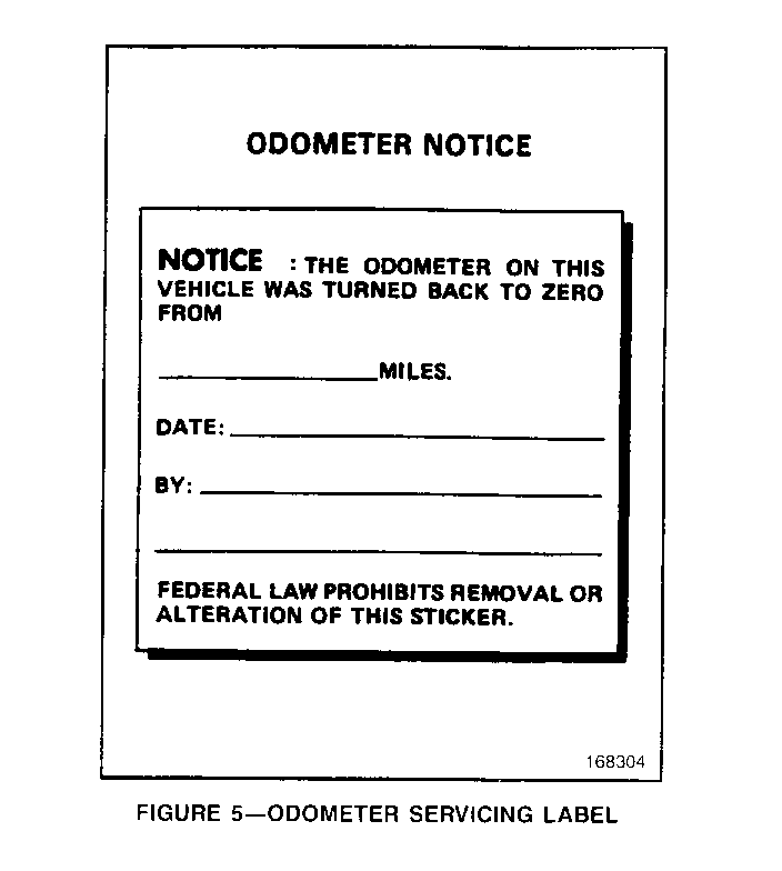
Various laws require that when an odometer is serviced, repaired or replaced, the mileage indicated is to remain the same as before this service, repair or replacement. Where the odometer cannot register the same mileage as before, the odometer shall be adjusted to read zero and an Odometer Servicing Label (Figure 5) shall be attached to the vehicle's left (driver's side) door frame. The prior mileage and the date of the repair or replacement are to be indicated on the label.
REMOVAL OF THE ODOMETER MODULE
1. Remove the instrument cluster assembly as described in the INSTRUMENT CLUSTER R&R procedure above. Place the cluster assembly on the bench under the conditions described in the ESD section of this bulletin!
2. Remove the five (5) screws around the perimeter of the lens.
3. Carefully lift off the lens and retainer as one piece, being careful not to damage the flex circuit (you do not need to remove the flex circuit to remove the lens and retainer).
Important
The flex circuit is not serviced separately.
4. Remove the screws from both left and right gauge clusters.
5. Lift the gauge clusters out of the cluster case.
6. Unplug the connector from the circuit board.
7. Remove the three (3) screws holding odometer module in place.
SETTING MILEAGE ON THE NEW ODOMETER
1. Remove the retainer from the end of the odometer shaft.
2. The drive gear is a snap fit and requires care when lifting the odometer.
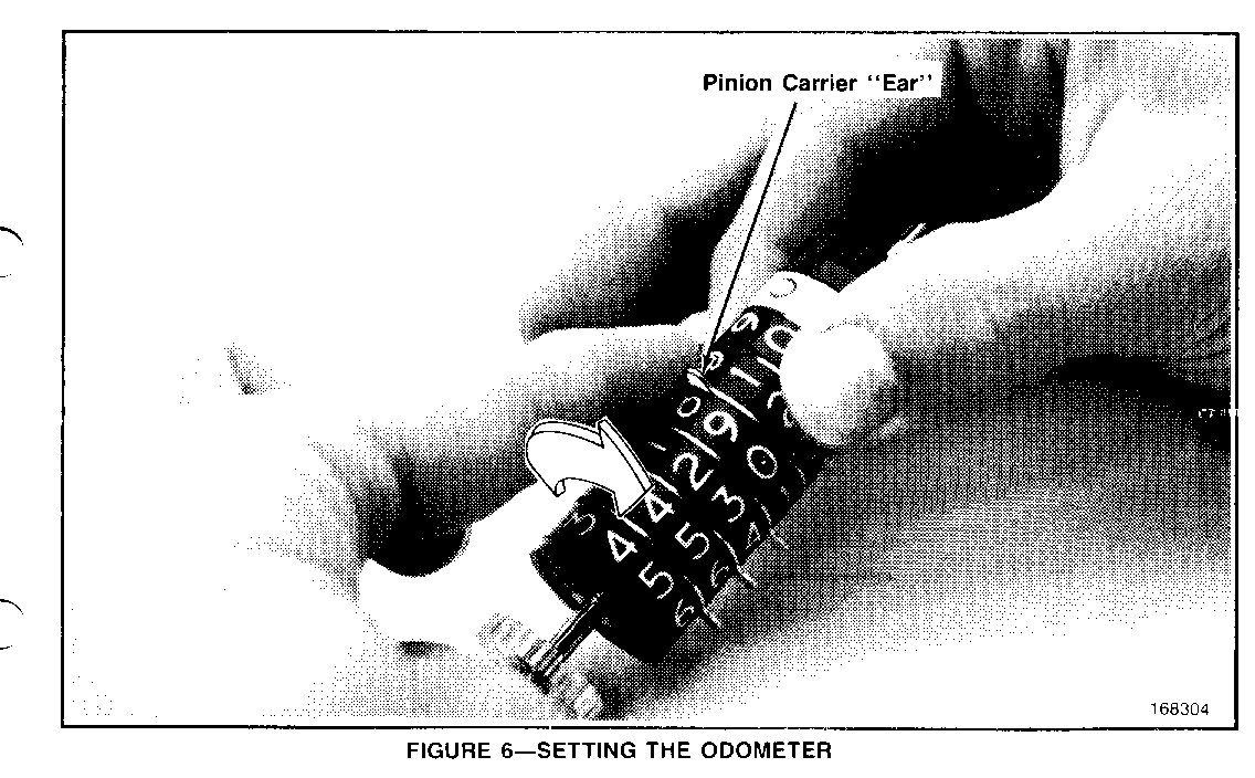
3. Note the position and alignment of the projecting ears of the pinion carriers (on the bottom or backside of the odometer wheels) The numerals exactly opposite these ears will appear in the odometer window. Use the tenths wheel numeral opposite these ears as a reference for setting the other wheels. Hold the first figure wheel (tenths) between your right thumb and index finger (Figure 6).
4. Remove the plastic carrier retainer from the projecting ears on the backside of the wheels.
5. With the left hand index finger, rotate the first ear (between the ones and tenths wheel) completely around and back into its original position. This will increment the "ones" wheel. The carrier must be rotated one (1) full turn for each increase of the number.
6. Continue rotating this carrier until the wheel indicates the desired figure as it would appear in the odometer window. The pinion carrier must end up in its original position (as if the plastic pinion carrier retainer were installed) for the correct number to be displayed.
7. Shift the right hand thumb and index finger to hold and keep in alignment the first figure wheel, the first pinion carrier and the second figure wheel.
8. With the left hand index finger, rotate the second pinion carrier until the third figure wheel indicates the desired figure. Continue working from right to left until each figure wheel is in its desired position. Then reinstall the plastic carrier retainer on the odometer.
WARNING:
IT IS AGAINST THE LAW AND GM POLICY TO SET A REPLACEMENT OR SERVICED ODOMETER TO ANY MILEAGE OTHER THAN ZERO OR THE ACTUAL VEHICLE MILEAGE!
9. Place the odometer in the module frame. When placing the odometer back into the frame, the pinion carrier ears must line up to fit in the odometer frame groove provided for them. Install the odometer shaft retaining clip.
INSTALLING THE NEW ODOMETER
1. Install the odometer module into the cluster case.
2. Plug the connector into the circuit board.
3. Install the two (2) screws. Torque the screws to 6.0 - 11.0 lbs. in. (0.7 N-m
4. Install the gauge clusters.
5. Install three (3) screws in each gauge cluster. Torque the screws to 6.0 - 1 1.0 lbs. in. (0.7 N-m ).
6. Install the lens and retainer.
7. Install the instrument cluster as described in the INSTRUMENT CLUSTER R&R procedure above.
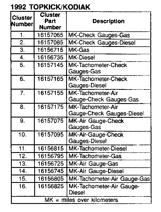
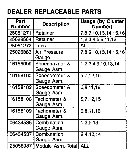
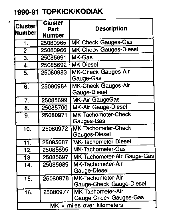
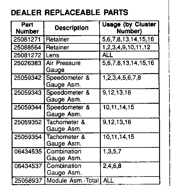
SERVICE PARTS INFORMATION
Important
Parts are available only for the instrument clusters listed below. Please note: Processor boards and flex (printed) circuits are not serviced separately.
Important
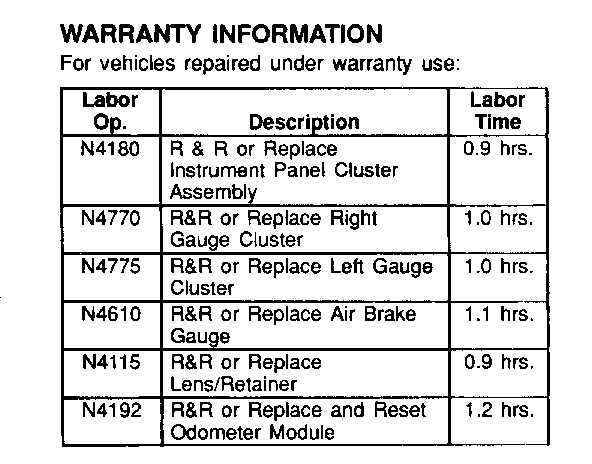
All Labor Times listed above include Labor Operation N4180
General Motors bulletins are intended for use by professional technicians, not a "do-it-yourselfer". They are written to inform those technicians of conditions that may occur on some vehicles, or to provide information that could assist in the proper service of a vehicle. Properly trained technicians have the equipment, tools, safety instructions and know-how to do a job properly and safely. If a condition is described, do not assume that the bulletin applies to your vehicle, or that your vehicle will have that condition. See a General Motors dealer servicing your brand of General Motors vehicle for information on whether your vehicle may benefit from the information.
