SERVICE MAN. UPDATE-SEC. 101A DOOR HINGE PIN BUSHING REPL.

SUBJECT: SECTION 10A1 - DOOR HINGE PIN BUSHING REPLACEMENT (NEW PROCEDURE)
VEHICLES AFFECTED: 1990-92 "C" MEDIUM DUTY MODEL
The following represents new information for Section 10A1 of the 1990-922 Medium Duty Models Service Manual.
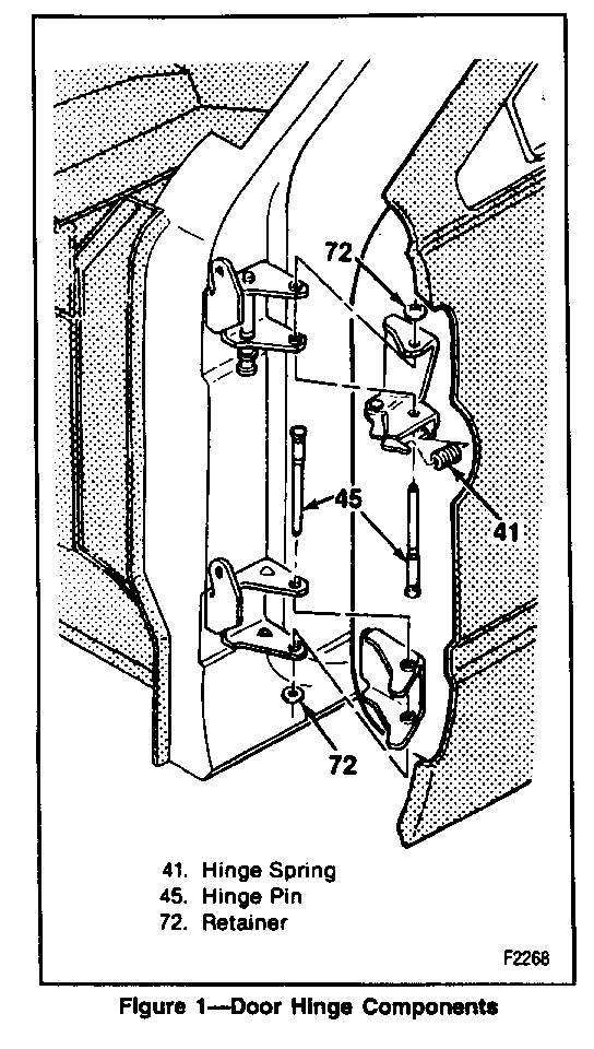
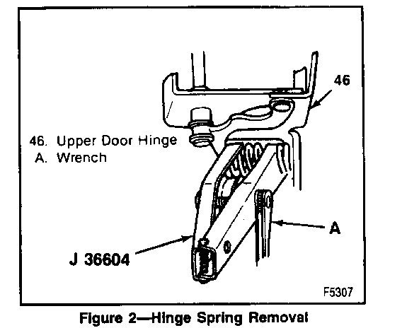
REMOVE OR DISCONNECT: (Figures 1 and 2) -------------------- Tools Required:
J 36604 Door Hinge Spring Compressor
VEHICLES WITH POWER DOOR COMPONENTS ONLY:
1. Negative battery cable.
2. Kick panel trim.
3. Wiring harness connectors under the dash.
(a) Receptacles from the wiring harness.
(b) Retainer from the wiring harness grommet.
(c) Rubber conduit from the door pillar by pushing it from the vent cover side.
ALL VEHICLES:
Apply cloth backed tape to the door, and the body pillar to guard against nicks and scratches.
CAUTION:
Before performing the following step, cover the spring with a towel to prevent the spring from dislodging and possibly causing personal injury or damage.
4. Door hinge spring using J 36604.
o Insert the blades of the tool between the spring coils and turn the barrel nut to compress and hold the spring during removal.
5. Lower hinge pin retainer.
CAUTION:
Have a helper ready to support the door to prevent the door from failing and result in personal injury or damage.
6. Lower hinge pin using locking pliers and a soft-faced hammer.
o Install a bolt temporarily through the lower hinges to hold the door in place while removing the upper hinge pin.
7. Upper hinge pin retainer.
8. Upper hinge pin.
9. Bolt in lower hinge pin hole.
10. Door from the vehicle.
11. Bushings from hinge using a hammer and chisel.
o Note which bushing has a larger inside diameter.
INSTALL OR CONNECT:
Tool Required:
J 36604 Door Hinge Spring Compressor
1. Upper and lower bushings to both hinges.
o Bushing with larger inside diameter goes in the top position on the upper hinge.
o Bushing with larger inside diameter goes in the lower position on the lower hinge.
o Shoulder on upper bushing must face up.
o Shoulder on lower bushing must face down.
2. Door to vehicle.
3. Bolt through the lower hinge pin holes.
4. Upper hinge pin with the pointed end up.
5. New hinge pin retainer using a locking pliers and a soft-faced hammer.
o Remove the bolt from the lower hinge.
6. Lower hinge pin with the pointed edge down.
7. New hinge pin retainer.
8. Door hinge spring using J 36604
9. Wiring harness connectors (Vehicles with power components only).
(a) Rubber conduit through the body pillar.
(b) Retainer around the wire harness grommet.
(c) Receptacles to the wiring harness under the dash.
10. Kick panel trim.
11. Negative battery cable.


General Motors bulletins are intended for use by professional technicians, not a "do-it-yourselfer". They are written to inform those technicians of conditions that may occur on some vehicles, or to provide information that could assist in the proper service of a vehicle. Properly trained technicians have the equipment, tools, safety instructions and know-how to do a job properly and safely. If a condition is described, do not assume that the bulletin applies to your vehicle, or that your vehicle will have that condition. See a General Motors dealer servicing your brand of General Motors vehicle for information on whether your vehicle may benefit from the information.
